
User's Manual
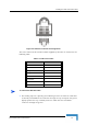
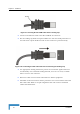
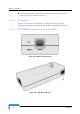
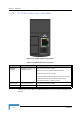
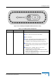
Table Of Contents
- BreezeMAX CPEs Product Manual
- About This Manual
- Contents
- Figures
- Tables
- Chapter 1 - Products Description
- Chapter 2 - Installation
- 2.1 Installing the ODU of the PRO-S CPE
- 2.2 Installing the IDU-1D Indoor Unit of the PRO-S CPE
- 2.3 Installing the Si CPE
- 2.4 Installing the 3.5 GHz Detached Antenna
- 2.5 Installing the 2.3/2.5 GHz Detached Antenna
- Chapter 3 - Commissioning
- Chapter 4 - Operation
- 4.1 The SU Installer Monitor Program
- 4.2 Using the Monitor Program
- 4.3 The Main Menu
- 4.4 Unit Control Menu
- 4.5 Registration Parameters Menu
- 4.6 BST/AU ID Parameters Menu
- 4.7 ˘Radio Parameters Menu
- 4.8 Performance Monitoring Menu
- 4.9 Multirate and ATPC Parameters Menu
- 4.10 ˘SU Parameters Summary
- Appendix A - The Web Configuration Server
- Appendix B - Troubleshooting
- Glossary

38 Installation
Chapter 2 - Installation
2.3.2 Si CPE Connectors and LEDs
* After power-up, the Ethernet LEDs illuminate for a few seconds until self-test is
finished.
Figure 2-11: Si CPE Connectors (E model)
Table 2-6: Si CPE Front Panel Connectors
Name Connector Functionality
ETHERNET
(E model)
10/100Base-T (RJ-45) with
2 embedded LEDs
Connection to the user's LAN/PC
Cable connection to a hub/switch/router: Crossed
Cable connection to a PC: Straight
Green LED: Ethernet Integrity. Ethernet connection detected.
Yellow LED: Ethernet Activity indication. Blinks during
transmission/reception of Ethernet packets.
USB (U model) USB 1.1/2.0 connector Connection to the user's LAN/PC
POWER DC Power Jack Connection to Power Adapter