
User's Manual
Installing the Base Transceiver Station (BTS) Equipment
4Motion System Manual 65
Other installation tools and materials
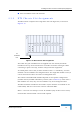
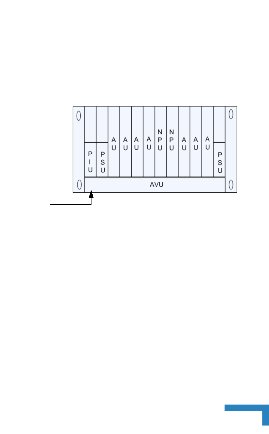
2.3.2 BTS Chassis Slot Assignments
The BTS chassis comprises 6 3U high slots and 9 6U high slots, as shown in
Figure 2-14.
The Cable Tray (the installation kit is supplied with the chassis) should be
installed on the top of the chassis front to enable convenient routing of cables
connecting to power source(s), outdoor unit(s) and other equipment.
To enable power source and/or Power Interface Unit 1+1 redundancy, two PIU
modules can be installed in the designated slots. If a single PIU module is used, it
can be inserted into either one of the two designated slots.
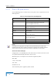
The number of installed PSU modules depends on the specific configuration
(number of AUs) and NPU redundancy scheme (refer to Table 2-9). If less than 4
PSU modules are used, they can be installed in any of the designated slots.
The NPU should be installed in slot number 5 (slot numbers are marked on the
Cable Guide). Slot 6 is reserved for a future redundant NPU.
Slots 1-4 and 7-9 can hold up to seven AU modules (only six AUs can be active).
Unused slots should remain covered until required.
Figure 2-14: BTS Chassis Slot Assignments
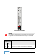
Air
Ventillation
Unit