
User's Manual
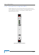
Table Of Contents
- BreezeMAX TDD Modular Base Station System Manual
- About This Manual
- Contents
- Figures
- Tables
- Chapter 1 - System Description
- 1.1 Introducing BreezeMAX
- 1.2 Base Station Equipment
- 1.3 Networking Equipment
- 1.4 Management Systems
- 1.5 Specifications
- 1.5.1 Radio
- 1.5.2 Base Station 2.X GHz Antennas (Optional)
- 1.5.3 Base Station 3.5 GHz Antennas (Optional)
- 1.5.4 ˘AU-IDU to AU-ODU Communication
- 1.5.5 Data Communication (Ethernet Ports)
- 1.5.6 Configuration and Management
- 1.5.7 Standards Compliance, General
- 1.5.8 Environmental
- 1.5.9 Services
- 1.5.10 Physical and Electrical
- Chapter 2 - Installation Guidelines
- 2.1 Installing the AU-ODU
- 2.2 Installing the Base Station Equipment
- 2.2.1 BST Installation Requirements
- 2.2.2 BMAX-BST-SH Chassis Slot Assignments
- 2.2.3 Power Requirements
- 2.2.4 HOT SWAP Support
- 2.2.5 Power Interface Unit (PIU)
- 2.2.6 Power Supply Unit (PSU)
- 2.2.7 Access Unit Indoor Module (AU-IDU)
- 2.2.8 Network Processing Unit (NPU)
- 2.2.9 Using the Hot Swap Injector/Ejector Handles
- 2.2.10 Installing the Base Station Chassis and Modules
- 2.2.11 Air Ventilation Unit (AVU)
- 2.3 Installing the ODU Power Feeder
- 2.4 Installing the GPS Adapter
- Chapter 3 - Commissioning
- Chapter 4 - Operation and Administration
- 4.1 BreezeMAX System Management
- 4.2 The Monitor Program
- 4.3 ˘The NPU's Main Menu
- 4.4 Base Station Menu
- 4.5 ˘NPU Menu
- 4.6 Radio Cluster Menu
- 4.7 ODU Menu
- 4.8 AU Menu
- 4.8.1 Show Summary
- 4.8.2 Upgrading AU’s SW
- 4.8.3 SW Files in NPU
- 4.8.4 Select
- 4.8.5 AU Slot # Menu
- 4.8.6 Performance Monitoring
- 4.9 SU Menu
- 4.9.1 Show Summary
- 4.9.2 Show Summary by AU
- 4.9.3 Upgrading SU’s SW
- 4.9.4 ˘SW Files in NPU
- 4.9.5 Select by Name
- 4.9.6 Select by MAC Address
- 4.9.7 SU # Menu
- 4.9.7.1 Show
- 4.9.7.2 Unit Control
- 4.9.7.3 Configuration
- 4.9.7.3.1 Registration Parameters
- 4.9.7.3.2 MAC Parameters
- 4.9.7.3.3 Phy Parameters
- 4.9.7.3.4 Multirate and ATPC Parameters
- 4.9.7.3.5 Voice/Networking Gateways
- 4.9.7.3.6 Ethernet Port
- 4.9.7.3.7 Installer Password
- 4.9.7.3.8 ˘Bridging Parameters
- 4.9.7.3.9 License
- 4.9.7.3.10 Best BST/AU
- 4.9.7.3.11 Frequency Scanning
- 4.9.7.4 Performance Monitoring
- 4.9.7.5 Show MAC Addresses Behind SU
- 4.9.7.6 Delete
- 4.9.8 Add New SU
- 4.9.9 Clear All Configured SU SW Files
- 4.10 Services Menu
- 4.10.1 Introduction to Services
- 4.10.2 Introduction to Filtering Features
- 4.10.3 Common Operations in Services Menu
- 4.10.4 The Services Menu
- 4.10.4.1 General
- 4.10.4.2 Subscribers
- 4.10.4.3 Services
- 4.10.4.4 Service Profiles
- 4.10.4.4.1 Service Profile Name
- 4.10.4.4.2 Service Type
- 4.10.4.4.3 VLAN Transparency Mode
- 4.10.4.4.4 VPL ID
- 4.10.4.4.5 Priority Marking Mode
- 4.10.4.4.6 Priority Marking Value
- 4.10.4.4.7 Forwarding Rule
- 4.10.4.4.8 Priority Classifier (L2 and PPPoE Service Type)
- 4.10.4.4.9 Maximum Number of Voice Calls (L2 and Voice Service Type)
- 4.10.4.4.10 Service Profile Class
- 4.10.4.5 Forwarding Rules
- 4.10.4.5.1 Forwarding Rule Name
- 4.10.4.5.2 Service Type
- 4.10.4.5.3 Unicast Relaying (L2 and Voice Service Type)
- 4.10.4.5.4 Broadcast Relaying (L2 and Voice Service Type)
- 4.10.4.5.5 Unknown Forwarding Policy (L2 and Voice Services Type)
- 4.10.4.5.6 Multicast VLAN ID
- 4.10.4.5.7 Multicast QoS Profile
- 4.10.4.5.8 Forwarding Rule Class
- 4.10.4.6 Priority Classifiers (L2 and PPPoE Service Type)
- 4.10.4.7 QoS Profiles
- 4.10.4.8 Filtering Rules
- 4.10.4.9 Interface Filtering
- 4.10.4.10 Filtering Examples
- 4.10.4.11 MAC Addresses Deny List
- 4.10.4.12 XML File Parsing Errors
- 4.10.5 Defining Local Service Profiles
- 4.10.6 Defining Local Services
- 4.10.7 Defining RADIUS Based Services
- 4.10.8 Pre-configured Profiles
- 4.11 NPU Parameters Summary
- Appendix A - Software Upgrade
- Appendix B - Defining Service Profiles for Generic VoIP Gateways
- Glossary
- Index

Installing the Base Station Equipment
BreezeMAX Modular Base Station System Manual 51
length of the Ethernet cable is 100m when operating at 100 Mbps and 70m
when operating at 1 Gbps.
7 If the MGMT port will be used for remote management, connect it to the
appropriate data equipment (use a straight Ethernet cable to connect to a
hub/switch/router). The maximum length of the Ethernet cable is 100m.
8 Connect the DC power cable to the power jack of the PIU module. If a
redundant PIU is installed, connect a DC power cable also to the second PIU
module. Connect the power cord(s) to the 48 VDC power source(s), as follows.
Connect the black wire to the 48 VDC contact of the power source.
Connect the red wire to the + (Return) contact.
Connect the ground wire to the ground.
9 For AU-ODUs that connect directly to AU-IDUs: Connect the IF cable(s)
(already connected at the other end to the AU-ODU(s)) to the proper channels
(ODU 1 to ODU 4 connectors) of the applicable AU-IDU module(s). If only a
single AU-ODU per AU-IDU is used, connect the IF cable(s) to the appropriate
ODU-1 connector(s). To avoid transmissions at undesired frequencies, verify
that the frequency and bandwidth parameters are properly configured before
connecting the IF cables.
For AU-ODU that are powered by a Power Feeder: Refer to Section 2.3.3.
CAUTION
A maximum of six AU-ODU-HP units can be powered directly from the Base Station (via the ODU
connectors of AU-IDUs). Additional AU-ODU-HP units shauld be powered by ODU Power
Feeder(s).