
User's Manual
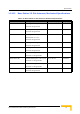

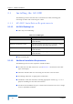
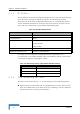

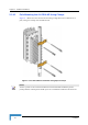
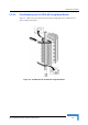
Table Of Contents
- BreezeMAX TDD Modular Base Station System Manual
- About This Manual
- Contents
- Figures
- Tables
- Chapter 1 - System Description
- 1.1 Introducing BreezeMAX
- 1.2 Base Station Equipment
- 1.3 Networking Equipment
- 1.4 Management Systems
- 1.5 Specifications
- 1.5.1 Radio
- 1.5.2 Base Station 2.X GHz Antennas (Optional)
- 1.5.3 Base Station 3.5 GHz Antennas (Optional)
- 1.5.4 ˘AU-IDU to AU-ODU Communication
- 1.5.5 Data Communication (Ethernet Ports)
- 1.5.6 Configuration and Management
- 1.5.7 Standards Compliance, General
- 1.5.8 Environmental
- 1.5.9 Services
- 1.5.10 Physical and Electrical
- Chapter 2 - Installation Guidelines
- 2.1 Installing the AU-ODU
- 2.2 Installing the Base Station Equipment
- 2.2.1 BST Installation Requirements
- 2.2.2 BMAX-BST-SH Chassis Slot Assignments
- 2.2.3 Power Requirements
- 2.2.4 HOT SWAP Support
- 2.2.5 Power Interface Unit (PIU)
- 2.2.6 Power Supply Unit (PSU)
- 2.2.7 Access Unit Indoor Module (AU-IDU)
- 2.2.8 Network Processing Unit (NPU)
- 2.2.9 Using the Hot Swap Injector/Ejector Handles
- 2.2.10 Installing the Base Station Chassis and Modules
- 2.2.11 Air Ventilation Unit (AVU)
- 2.3 Installing the ODU Power Feeder
- 2.4 Installing the GPS Adapter
- Chapter 3 - Commissioning
- Chapter 4 - Operation and Administration
- 4.1 BreezeMAX System Management
- 4.2 The Monitor Program
- 4.3 ˘The NPU's Main Menu
- 4.4 Base Station Menu
- 4.5 ˘NPU Menu
- 4.6 Radio Cluster Menu
- 4.7 ODU Menu
- 4.8 AU Menu
- 4.8.1 Show Summary
- 4.8.2 Upgrading AU’s SW
- 4.8.3 SW Files in NPU
- 4.8.4 Select
- 4.8.5 AU Slot # Menu
- 4.8.6 Performance Monitoring
- 4.9 SU Menu
- 4.9.1 Show Summary
- 4.9.2 Show Summary by AU
- 4.9.3 Upgrading SU’s SW
- 4.9.4 ˘SW Files in NPU
- 4.9.5 Select by Name
- 4.9.6 Select by MAC Address
- 4.9.7 SU # Menu
- 4.9.7.1 Show
- 4.9.7.2 Unit Control
- 4.9.7.3 Configuration
- 4.9.7.3.1 Registration Parameters
- 4.9.7.3.2 MAC Parameters
- 4.9.7.3.3 Phy Parameters
- 4.9.7.3.4 Multirate and ATPC Parameters
- 4.9.7.3.5 Voice/Networking Gateways
- 4.9.7.3.6 Ethernet Port
- 4.9.7.3.7 Installer Password
- 4.9.7.3.8 ˘Bridging Parameters
- 4.9.7.3.9 License
- 4.9.7.3.10 Best BST/AU
- 4.9.7.3.11 Frequency Scanning
- 4.9.7.4 Performance Monitoring
- 4.9.7.5 Show MAC Addresses Behind SU
- 4.9.7.6 Delete
- 4.9.8 Add New SU
- 4.9.9 Clear All Configured SU SW Files
- 4.10 Services Menu
- 4.10.1 Introduction to Services
- 4.10.2 Introduction to Filtering Features
- 4.10.3 Common Operations in Services Menu
- 4.10.4 The Services Menu
- 4.10.4.1 General
- 4.10.4.2 Subscribers
- 4.10.4.3 Services
- 4.10.4.4 Service Profiles
- 4.10.4.4.1 Service Profile Name
- 4.10.4.4.2 Service Type
- 4.10.4.4.3 VLAN Transparency Mode
- 4.10.4.4.4 VPL ID
- 4.10.4.4.5 Priority Marking Mode
- 4.10.4.4.6 Priority Marking Value
- 4.10.4.4.7 Forwarding Rule
- 4.10.4.4.8 Priority Classifier (L2 and PPPoE Service Type)
- 4.10.4.4.9 Maximum Number of Voice Calls (L2 and Voice Service Type)
- 4.10.4.4.10 Service Profile Class
- 4.10.4.5 Forwarding Rules
- 4.10.4.5.1 Forwarding Rule Name
- 4.10.4.5.2 Service Type
- 4.10.4.5.3 Unicast Relaying (L2 and Voice Service Type)
- 4.10.4.5.4 Broadcast Relaying (L2 and Voice Service Type)
- 4.10.4.5.5 Unknown Forwarding Policy (L2 and Voice Services Type)
- 4.10.4.5.6 Multicast VLAN ID
- 4.10.4.5.7 Multicast QoS Profile
- 4.10.4.5.8 Forwarding Rule Class
- 4.10.4.6 Priority Classifiers (L2 and PPPoE Service Type)
- 4.10.4.7 QoS Profiles
- 4.10.4.8 Filtering Rules
- 4.10.4.9 Interface Filtering
- 4.10.4.10 Filtering Examples
- 4.10.4.11 MAC Addresses Deny List
- 4.10.4.12 XML File Parsing Errors
- 4.10.5 Defining Local Service Profiles
- 4.10.6 Defining Local Services
- 4.10.7 Defining RADIUS Based Services
- 4.10.8 Pre-configured Profiles
- 4.11 NPU Parameters Summary
- Appendix A - Software Upgrade
- Appendix B - Defining Service Profiles for Generic VoIP Gateways
- Glossary
- Index

30 Installation
Chapter 2 - Installation Guidelines
2.1.3 IF Cables
The AU-ODU is connected to the Micro Base Station (or to the ODU Power Feeder)
via an IF cable carrying both signals and power. The maximum permitted
attenuation of the IF cable at applicable frequencies, its screening effectiveness
and its maximum permitted DC resistance (the sum of the DC resistance of the
inner and outer conductors) are provided in the following table.
To comply with the required screening effectiveness requirement, it is
recommended to use double shielded cables. The following table provides details
on maximum length for some popular cables.
2.1.4 Pole Mounting the ODU
The ODU can be mounted on a 1" to 4" pole using one of the following options:
Special clamps and threaded rods are supplied with each unit. There are two
pairs of threaded holes on the back of the unit, enabling to use the clamps for
mounting the unit on diverse pole diameters.
Table 2-2: IF Cables Requirements
Item Description
Screening Effectiveness 90 dB minimum in the 10-300 MHz band.
IF cable Impedance 50 ohm
Maximum IF cable Attenuation 10 dB @ 240 MHz
7.5 dB @ 140 MHz
8 dB @ 64 MHz
Maximum IF cable DC Resistance 1.5 ohm
Maximum IF cable Return Loss 20 dB in the 10-300 MHz band
Table 2-3: Maximum IF Cable Length (Double Shielded Cables)
Cable Maximum Length for AU-ODU-HP
LMR-195 30 meters
LMR-240 60 meters
LMR-400 150 meters