
User's Manual
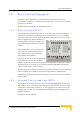
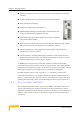
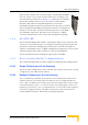
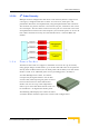
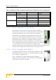
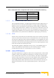
Table Of Contents
- BreezeMAX TDD Modular Base Station System Manual
- About This Manual
- Contents
- Figures
- Tables
- Chapter 1 - System Description
- 1.1 Introducing BreezeMAX
- 1.2 Base Station Equipment
- 1.3 Networking Equipment
- 1.4 Management Systems
- 1.5 Specifications
- 1.5.1 Radio
- 1.5.2 Base Station 2.X GHz Antennas (Optional)
- 1.5.3 Base Station 3.5 GHz Antennas (Optional)
- 1.5.4 ˘AU-IDU to AU-ODU Communication
- 1.5.5 Data Communication (Ethernet Ports)
- 1.5.6 Configuration and Management
- 1.5.7 Standards Compliance, General
- 1.5.8 Environmental
- 1.5.9 Services
- 1.5.10 Physical and Electrical
- Chapter 2 - Installation Guidelines
- 2.1 Installing the AU-ODU
- 2.2 Installing the Base Station Equipment
- 2.2.1 BST Installation Requirements
- 2.2.2 BMAX-BST-SH Chassis Slot Assignments
- 2.2.3 Power Requirements
- 2.2.4 HOT SWAP Support
- 2.2.5 Power Interface Unit (PIU)
- 2.2.6 Power Supply Unit (PSU)
- 2.2.7 Access Unit Indoor Module (AU-IDU)
- 2.2.8 Network Processing Unit (NPU)
- 2.2.9 Using the Hot Swap Injector/Ejector Handles
- 2.2.10 Installing the Base Station Chassis and Modules
- 2.2.11 Air Ventilation Unit (AVU)
- 2.3 Installing the ODU Power Feeder
- 2.4 Installing the GPS Adapter
- Chapter 3 - Commissioning
- Chapter 4 - Operation and Administration
- 4.1 BreezeMAX System Management
- 4.2 The Monitor Program
- 4.3 ˘The NPU's Main Menu
- 4.4 Base Station Menu
- 4.5 ˘NPU Menu
- 4.6 Radio Cluster Menu
- 4.7 ODU Menu
- 4.8 AU Menu
- 4.8.1 Show Summary
- 4.8.2 Upgrading AU’s SW
- 4.8.3 SW Files in NPU
- 4.8.4 Select
- 4.8.5 AU Slot # Menu
- 4.8.6 Performance Monitoring
- 4.9 SU Menu
- 4.9.1 Show Summary
- 4.9.2 Show Summary by AU
- 4.9.3 Upgrading SU’s SW
- 4.9.4 ˘SW Files in NPU
- 4.9.5 Select by Name
- 4.9.6 Select by MAC Address
- 4.9.7 SU # Menu
- 4.9.7.1 Show
- 4.9.7.2 Unit Control
- 4.9.7.3 Configuration
- 4.9.7.3.1 Registration Parameters
- 4.9.7.3.2 MAC Parameters
- 4.9.7.3.3 Phy Parameters
- 4.9.7.3.4 Multirate and ATPC Parameters
- 4.9.7.3.5 Voice/Networking Gateways
- 4.9.7.3.6 Ethernet Port
- 4.9.7.3.7 Installer Password
- 4.9.7.3.8 ˘Bridging Parameters
- 4.9.7.3.9 License
- 4.9.7.3.10 Best BST/AU
- 4.9.7.3.11 Frequency Scanning
- 4.9.7.4 Performance Monitoring
- 4.9.7.5 Show MAC Addresses Behind SU
- 4.9.7.6 Delete
- 4.9.8 Add New SU
- 4.9.9 Clear All Configured SU SW Files
- 4.10 Services Menu
- 4.10.1 Introduction to Services
- 4.10.2 Introduction to Filtering Features
- 4.10.3 Common Operations in Services Menu
- 4.10.4 The Services Menu
- 4.10.4.1 General
- 4.10.4.2 Subscribers
- 4.10.4.3 Services
- 4.10.4.4 Service Profiles
- 4.10.4.4.1 Service Profile Name
- 4.10.4.4.2 Service Type
- 4.10.4.4.3 VLAN Transparency Mode
- 4.10.4.4.4 VPL ID
- 4.10.4.4.5 Priority Marking Mode
- 4.10.4.4.6 Priority Marking Value
- 4.10.4.4.7 Forwarding Rule
- 4.10.4.4.8 Priority Classifier (L2 and PPPoE Service Type)
- 4.10.4.4.9 Maximum Number of Voice Calls (L2 and Voice Service Type)
- 4.10.4.4.10 Service Profile Class
- 4.10.4.5 Forwarding Rules
- 4.10.4.5.1 Forwarding Rule Name
- 4.10.4.5.2 Service Type
- 4.10.4.5.3 Unicast Relaying (L2 and Voice Service Type)
- 4.10.4.5.4 Broadcast Relaying (L2 and Voice Service Type)
- 4.10.4.5.5 Unknown Forwarding Policy (L2 and Voice Services Type)
- 4.10.4.5.6 Multicast VLAN ID
- 4.10.4.5.7 Multicast QoS Profile
- 4.10.4.5.8 Forwarding Rule Class
- 4.10.4.6 Priority Classifiers (L2 and PPPoE Service Type)
- 4.10.4.7 QoS Profiles
- 4.10.4.8 Filtering Rules
- 4.10.4.9 Interface Filtering
- 4.10.4.10 Filtering Examples
- 4.10.4.11 MAC Addresses Deny List
- 4.10.4.12 XML File Parsing Errors
- 4.10.5 Defining Local Service Profiles
- 4.10.6 Defining Local Services
- 4.10.7 Defining RADIUS Based Services
- 4.10.8 Pre-configured Profiles
- 4.11 NPU Parameters Summary
- Appendix A - Software Upgrade
- Appendix B - Defining Service Profiles for Generic VoIP Gateways
- Glossary
- Index

Base Station Equipment
BreezeMAX Modular Base Station System Manual 11
1.2.9 Air Ventilation Unit (AVU)
The 2U high AVU includes a 1U high integral chamber for inlet airflow and a 1U
high fan tray with an internal alarm module. To support high availability Base
Station, the fan tray includes 10 brush-less fans, where 9 fans are sufficient for
cooling a fully loaded chassis. A failure in any of the fans is indicated by both the
front panel LEDs and a trap that is sent to the management system. To further
support high availability, the chassis may operate with the hot-swappable fan tray
extracted from it for a period of time sufficient for replacing it (up 10 minutes).
1.2.10 GPS
GPS is used to synchronize the air link frames of Intra-site and Inter-site located
sectors to ensure that in all sectors the air frame will start at the same time, and
that all sectors will switch from transmit (downlink) to receive (uplink) at the same
time. This synchronization is necessary to prevent Intra-site and Inter-site sectors
interference and saturation (assuming that all sectors are operating with the same
frame size and with the same DL/UL ratio).
The GPS clock required is 1PPS with accuracy of 10
-11
and maximum jitter of
100ns. These GPS clock requirements can be reached by indoor or outdoor
installed GPS unit when it is synchronized to at least 4 satellites.
1.2.10.1 Indoor GPS Receiver
The Indoor GPS Receiver comprises a GPS receiver integrated with a stable OCXO
oscillator, within a unit designed for mounting in a standard 19 inch rack. A 50
meter coaxial cable connects it to an active antenna. The indoor installed GPS
system is able to provide up to 40 hours of clock holdover with a maximal drift of
50 microseconds when the GPS system losses satellites synchronization. The
Indoor GPS provides 1PPS at TTL levels and the control channel is driven by an
RS-232 serial interface. The unit is powered directly from a -48 VDC power
source.
Table 1-2: PSU Requirements, Configurations with one NPU (excluding PSU redundancy)
Number of AU-IDUs Minimum Required
Number of PSUs
1 - 2 1
3 - 4 2
5 - 6 3