
User's Manual
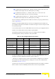
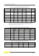
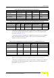
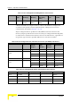
Table Of Contents
- BreezeMAX TDD Modular Base Station System Manual
- About This Manual
- Contents
- Figures
- Tables
- Chapter 1 - System Description
- 1.1 Introducing BreezeMAX
- 1.2 Base Station Equipment
- 1.3 Networking Equipment
- 1.4 Management Systems
- 1.5 Specifications
- 1.5.1 Radio
- 1.5.2 Base Station 2.X GHz Antennas (Optional)
- 1.5.3 Base Station 3.5 GHz Antennas (Optional)
- 1.5.4 ˘AU-IDU to AU-ODU Communication
- 1.5.5 Data Communication (Ethernet Ports)
- 1.5.6 Configuration and Management
- 1.5.7 Standards Compliance, General
- 1.5.8 Environmental
- 1.5.9 Services
- 1.5.10 Physical and Electrical
- Chapter 2 - Installation Guidelines
- 2.1 Installing the AU-ODU
- 2.2 Installing the Base Station Equipment
- 2.2.1 BST Installation Requirements
- 2.2.2 BMAX-BST-SH Chassis Slot Assignments
- 2.2.3 Power Requirements
- 2.2.4 HOT SWAP Support
- 2.2.5 Power Interface Unit (PIU)
- 2.2.6 Power Supply Unit (PSU)
- 2.2.7 Access Unit Indoor Module (AU-IDU)
- 2.2.8 Network Processing Unit (NPU)
- 2.2.9 Using the Hot Swap Injector/Ejector Handles
- 2.2.10 Installing the Base Station Chassis and Modules
- 2.2.11 Air Ventilation Unit (AVU)
- 2.3 Installing the ODU Power Feeder
- 2.4 Installing the GPS Adapter
- Chapter 3 - Commissioning
- Chapter 4 - Operation and Administration
- 4.1 BreezeMAX System Management
- 4.2 The Monitor Program
- 4.3 ˘The NPU's Main Menu
- 4.4 Base Station Menu
- 4.5 ˘NPU Menu
- 4.6 Radio Cluster Menu
- 4.7 ODU Menu
- 4.8 AU Menu
- 4.8.1 Show Summary
- 4.8.2 Upgrading AU’s SW
- 4.8.3 SW Files in NPU
- 4.8.4 Select
- 4.8.5 AU Slot # Menu
- 4.8.6 Performance Monitoring
- 4.9 SU Menu
- 4.9.1 Show Summary
- 4.9.2 Show Summary by AU
- 4.9.3 Upgrading SU’s SW
- 4.9.4 ˘SW Files in NPU
- 4.9.5 Select by Name
- 4.9.6 Select by MAC Address
- 4.9.7 SU # Menu
- 4.9.7.1 Show
- 4.9.7.2 Unit Control
- 4.9.7.3 Configuration
- 4.9.7.3.1 Registration Parameters
- 4.9.7.3.2 MAC Parameters
- 4.9.7.3.3 Phy Parameters
- 4.9.7.3.4 Multirate and ATPC Parameters
- 4.9.7.3.5 Voice/Networking Gateways
- 4.9.7.3.6 Ethernet Port
- 4.9.7.3.7 Installer Password
- 4.9.7.3.8 ˘Bridging Parameters
- 4.9.7.3.9 License
- 4.9.7.3.10 Best BST/AU
- 4.9.7.3.11 Frequency Scanning
- 4.9.7.4 Performance Monitoring
- 4.9.7.5 Show MAC Addresses Behind SU
- 4.9.7.6 Delete
- 4.9.8 Add New SU
- 4.9.9 Clear All Configured SU SW Files
- 4.10 Services Menu
- 4.10.1 Introduction to Services
- 4.10.2 Introduction to Filtering Features
- 4.10.3 Common Operations in Services Menu
- 4.10.4 The Services Menu
- 4.10.4.1 General
- 4.10.4.2 Subscribers
- 4.10.4.3 Services
- 4.10.4.4 Service Profiles
- 4.10.4.4.1 Service Profile Name
- 4.10.4.4.2 Service Type
- 4.10.4.4.3 VLAN Transparency Mode
- 4.10.4.4.4 VPL ID
- 4.10.4.4.5 Priority Marking Mode
- 4.10.4.4.6 Priority Marking Value
- 4.10.4.4.7 Forwarding Rule
- 4.10.4.4.8 Priority Classifier (L2 and PPPoE Service Type)
- 4.10.4.4.9 Maximum Number of Voice Calls (L2 and Voice Service Type)
- 4.10.4.4.10 Service Profile Class
- 4.10.4.5 Forwarding Rules
- 4.10.4.5.1 Forwarding Rule Name
- 4.10.4.5.2 Service Type
- 4.10.4.5.3 Unicast Relaying (L2 and Voice Service Type)
- 4.10.4.5.4 Broadcast Relaying (L2 and Voice Service Type)
- 4.10.4.5.5 Unknown Forwarding Policy (L2 and Voice Services Type)
- 4.10.4.5.6 Multicast VLAN ID
- 4.10.4.5.7 Multicast QoS Profile
- 4.10.4.5.8 Forwarding Rule Class
- 4.10.4.6 Priority Classifiers (L2 and PPPoE Service Type)
- 4.10.4.7 QoS Profiles
- 4.10.4.8 Filtering Rules
- 4.10.4.9 Interface Filtering
- 4.10.4.10 Filtering Examples
- 4.10.4.11 MAC Addresses Deny List
- 4.10.4.12 XML File Parsing Errors
- 4.10.5 Defining Local Service Profiles
- 4.10.6 Defining Local Services
- 4.10.7 Defining RADIUS Based Services
- 4.10.8 Pre-configured Profiles
- 4.11 NPU Parameters Summary
- Appendix A - Software Upgrade
- Appendix B - Defining Service Profiles for Generic VoIP Gateways
- Glossary
- Index

Services Menu
BreezeMAX Modular Base Station System Manual 213
* VPL IDs are assigned arbitrary values and should be configured in accordance
with specific network implementation, taking into account the considerations
described in Section 4.10.1.6.
** To properly support Call Waiting, an additional connection must be available.
Thus, the Maximum Number of Voice Calls is twice the maximum expected
number of actual voice sessions.
In all pre-configured Service Profiles for generic VoIP services, the Priority Marking
Mode is set to Transparent and the Maximum Number of Voice Calls is 0.
* VPL IDs are assigned arbitrary values and should be configured in accordance
with specific network implementation, taking into account the considerations
described in Section 4.10.1.6.
NRT 128/192 Non Real Time 128 192 Medium
NRT 750/850 Non Real Time 750 850 Medium
NRT 1000/1150 Non Real Time 1000 1150 Medium
NRT 1500/1750 Non Real Time 1500 1750 Medium
Table 4-15: Pre-Configured Voice Service Profiles (for DRAP-based Gateways)
Name Service
Type
VPL
ID*
Priority
Marking Mode
Maximum Number
of Voice Calls**
Forwarding
Rule
VoIP 1V Voice 18 Transparent 2 VoIP
VoIP 2V Voice 18 Transparent 4 VoIP
Table 4-16: Pre-Configured Service Profiles for Generic (non-DRAP) VoIP Services
Name Service
Type
VPL ID* Forwarding
Rule
Priority Classifier
1 POTS Basic VoIP G.729 L2 19 VoIP 1 POTS Basic VoIP G.729
1 POTS Advanced VoIP
G.729
L2 19 VoIP 1 POTS Advanced VoIP
G.729
1 POTS Basic VoIP G.711 L2 19 VoIP 1 POTS Basic VoIP G.711
1 POTS Advanced VoIP
G.711
L2 19 VoIP 1 POTS Advanced VoIP
G.711
Table 4-14: Pre-Configured QoS Profiles for Data Services
Name Type CIR (Kbps) MIR (Kbps) CT