
User's Manual
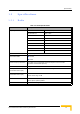
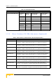
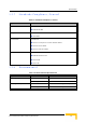
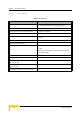
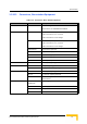
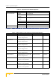
Table Of Contents
- BreezeMAX TDD Modular Base Station System Manual
- About This Manual
- Contents
- Figures
- Tables
- Chapter 1 - System Description
- 1.1 Introducing BreezeMAX
- 1.2 Base Station Equipment
- 1.3 Networking Equipment
- 1.4 Management Systems
- 1.5 Specifications
- 1.5.1 Radio
- 1.5.2 Base Station 2.X GHz Antennas (Optional)
- 1.5.3 Base Station 3.5 GHz Antennas (Optional)
- 1.5.4 ˘AU-IDU to AU-ODU Communication
- 1.5.5 Data Communication (Ethernet Ports)
- 1.5.6 Configuration and Management
- 1.5.7 Standards Compliance, General
- 1.5.8 Environmental
- 1.5.9 Services
- 1.5.10 Physical and Electrical
- Chapter 2 - Installation Guidelines
- 2.1 Installing the AU-ODU
- 2.2 Installing the Base Station Equipment
- 2.2.1 BST Installation Requirements
- 2.2.2 BMAX-BST-SH Chassis Slot Assignments
- 2.2.3 Power Requirements
- 2.2.4 HOT SWAP Support
- 2.2.5 Power Interface Unit (PIU)
- 2.2.6 Power Supply Unit (PSU)
- 2.2.7 Access Unit Indoor Module (AU-IDU)
- 2.2.8 Network Processing Unit (NPU)
- 2.2.9 Using the Hot Swap Injector/Ejector Handles
- 2.2.10 Installing the Base Station Chassis and Modules
- 2.2.11 Air Ventilation Unit (AVU)
- 2.3 Installing the ODU Power Feeder
- 2.4 Installing the GPS Adapter
- Chapter 3 - Commissioning
- Chapter 4 - Operation and Administration
- 4.1 BreezeMAX System Management
- 4.2 The Monitor Program
- 4.3 ˘The NPU's Main Menu
- 4.4 Base Station Menu
- 4.5 ˘NPU Menu
- 4.6 Radio Cluster Menu
- 4.7 ODU Menu
- 4.8 AU Menu
- 4.8.1 Show Summary
- 4.8.2 Upgrading AU’s SW
- 4.8.3 SW Files in NPU
- 4.8.4 Select
- 4.8.5 AU Slot # Menu
- 4.8.6 Performance Monitoring
- 4.9 SU Menu
- 4.9.1 Show Summary
- 4.9.2 Show Summary by AU
- 4.9.3 Upgrading SU’s SW
- 4.9.4 ˘SW Files in NPU
- 4.9.5 Select by Name
- 4.9.6 Select by MAC Address
- 4.9.7 SU # Menu
- 4.9.7.1 Show
- 4.9.7.2 Unit Control
- 4.9.7.3 Configuration
- 4.9.7.3.1 Registration Parameters
- 4.9.7.3.2 MAC Parameters
- 4.9.7.3.3 Phy Parameters
- 4.9.7.3.4 Multirate and ATPC Parameters
- 4.9.7.3.5 Voice/Networking Gateways
- 4.9.7.3.6 Ethernet Port
- 4.9.7.3.7 Installer Password
- 4.9.7.3.8 ˘Bridging Parameters
- 4.9.7.3.9 License
- 4.9.7.3.10 Best BST/AU
- 4.9.7.3.11 Frequency Scanning
- 4.9.7.4 Performance Monitoring
- 4.9.7.5 Show MAC Addresses Behind SU
- 4.9.7.6 Delete
- 4.9.8 Add New SU
- 4.9.9 Clear All Configured SU SW Files
- 4.10 Services Menu
- 4.10.1 Introduction to Services
- 4.10.2 Introduction to Filtering Features
- 4.10.3 Common Operations in Services Menu
- 4.10.4 The Services Menu
- 4.10.4.1 General
- 4.10.4.2 Subscribers
- 4.10.4.3 Services
- 4.10.4.4 Service Profiles
- 4.10.4.4.1 Service Profile Name
- 4.10.4.4.2 Service Type
- 4.10.4.4.3 VLAN Transparency Mode
- 4.10.4.4.4 VPL ID
- 4.10.4.4.5 Priority Marking Mode
- 4.10.4.4.6 Priority Marking Value
- 4.10.4.4.7 Forwarding Rule
- 4.10.4.4.8 Priority Classifier (L2 and PPPoE Service Type)
- 4.10.4.4.9 Maximum Number of Voice Calls (L2 and Voice Service Type)
- 4.10.4.4.10 Service Profile Class
- 4.10.4.5 Forwarding Rules
- 4.10.4.5.1 Forwarding Rule Name
- 4.10.4.5.2 Service Type
- 4.10.4.5.3 Unicast Relaying (L2 and Voice Service Type)
- 4.10.4.5.4 Broadcast Relaying (L2 and Voice Service Type)
- 4.10.4.5.5 Unknown Forwarding Policy (L2 and Voice Services Type)
- 4.10.4.5.6 Multicast VLAN ID
- 4.10.4.5.7 Multicast QoS Profile
- 4.10.4.5.8 Forwarding Rule Class
- 4.10.4.6 Priority Classifiers (L2 and PPPoE Service Type)
- 4.10.4.7 QoS Profiles
- 4.10.4.8 Filtering Rules
- 4.10.4.9 Interface Filtering
- 4.10.4.10 Filtering Examples
- 4.10.4.11 MAC Addresses Deny List
- 4.10.4.12 XML File Parsing Errors
- 4.10.5 Defining Local Service Profiles
- 4.10.6 Defining Local Services
- 4.10.7 Defining RADIUS Based Services
- 4.10.8 Pre-configured Profiles
- 4.11 NPU Parameters Summary
- Appendix A - Software Upgrade
- Appendix B - Defining Service Profiles for Generic VoIP Gateways
- Glossary
- Index

22 System Description
Chapter 1 - System Description
ODU Power Feeder Power Source: -40.5 to -60 VDC
Power Dissipation: 2W per channel
Chassis with 3 AU-IDUs (excluding
ODUs and Power Feeders)
310W maximum (1 NPU, 3 AU-IDUs, 1+1 PIUs, 2+1 PSUs)
Base station with 3 AU-IDUs, including
1 ODU per AU-IDU
555W maximum (1 NPU, 3 AU-IDUs with 1 ODU per AU-IDU, 1+1 PIUs,
2+1 PSUs)
Base station with 3 AU-IDUs, including
2 ODUs per AU-IDU
800W maximum (1 NPU, 3 AU-IDUs with 2 ODUs per AU-IDU, 1+1
PIUs, 2+1 PSUs)
Base station with 3 AU-IDUs, including
4 ODUs per AU-IDU
1300W maximum (1 NPU, 3 AU-IDUs with 4 ODUs per AU-IDU, 1+1
PIUs, 2+1 PSUs, 2 Power Feeders)
Chassis with 4 AU-IDUs (excluding
ODUs and Power Feeders)
366W maximum (1 NPU, 4 AU-IDUs, 1+1 PIUs, 2+1 PSUs)
Base station with 4 AU-IDUs, including
1 ODU per AU-IDU
690W maximum (1 NPU, 4 AU-IDUs with 1 ODU per AU-IDU, 1+1 PIUs,
2+1 PSUs)
Base station with 4 AU-IDUs, including
2 ODUs per AU-IDU
1025W maximum (1 NPU, 4 AU-IDUs with 2 ODUs per AU-IDU, 1+1
PIUs, 2+1 PSUs, 1 Power Feeder)
Base station with 4 AU-IDUs, including
4 ODUs per AU-IDU
1700W maximum (1 NPU, 4 AU-IDUs with 4 ODUs per AU-IDU, 1+1
PIUs, 2+1 PSUs, 3 Power Feeders)
Full Chassis with 6 AU-IDUs (excluding
ODUs and Power Feeders)
480W maximum (1 NPU, 6 AU-IDUs, 1+1 PIUs, 3+1 PSUs)
Full Base station with 6 AU-IDUs,
including 1 ODU per AU-IDU
975W maximum (1 NPU, 6 AU-IDUs with 1 ODU per AU-IDU, 1+1 PIUs,
3+1 PSUs)
Full Base station with 6 AU-IDUs,
including 2 ODUs per AU-IDU
1480W maximum (1 NPU, 6 AU-IDUs with 2 ODUs per AU-IDU, 1+1
PIUs, 3+1 PSUs, 2 Power Feeders)
Base station with 6 AU-IDUs, including
4 ODUs per AU-IDU
2500W maximum (1 NPU, 6 AU-IDUs with 4 ODUs per AU-IDU, 1+1
PIUs, 3+1 PSUs, 5 Power Feeders)
GPS Adapter 12 VDC from the NPU, 1.2W maximum
Indoor GPS Receiver Power Source: -36 to -72 VDC
Power Dissipation: 20W maximum, 12W typical
Outdoor GPS Receiver 12 VDC from the NPU via the GPS Adapter, 6W maximum
Table 1-13: Electrical Specifications, Base Station Equipment
Unit Details