
User's Manual
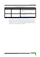

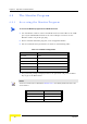

Table Of Contents
- BreezeMAX TDD Modular Base Station System Manual
- About This Manual
- Contents
- Figures
- Tables
- Chapter 1 - System Description
- 1.1 Introducing BreezeMAX
- 1.2 Base Station Equipment
- 1.3 Networking Equipment
- 1.4 Management Systems
- 1.5 Specifications
- 1.5.1 Radio
- 1.5.2 Base Station 2.X GHz Antennas (Optional)
- 1.5.3 Base Station 3.5 GHz Antennas (Optional)
- 1.5.4 ˘AU-IDU to AU-ODU Communication
- 1.5.5 Data Communication (Ethernet Ports)
- 1.5.6 Configuration and Management
- 1.5.7 Standards Compliance, General
- 1.5.8 Environmental
- 1.5.9 Services
- 1.5.10 Physical and Electrical
- Chapter 2 - Installation Guidelines
- 2.1 Installing the AU-ODU
- 2.2 Installing the Base Station Equipment
- 2.2.1 BST Installation Requirements
- 2.2.2 BMAX-BST-SH Chassis Slot Assignments
- 2.2.3 Power Requirements
- 2.2.4 HOT SWAP Support
- 2.2.5 Power Interface Unit (PIU)
- 2.2.6 Power Supply Unit (PSU)
- 2.2.7 Access Unit Indoor Module (AU-IDU)
- 2.2.8 Network Processing Unit (NPU)
- 2.2.9 Using the Hot Swap Injector/Ejector Handles
- 2.2.10 Installing the Base Station Chassis and Modules
- 2.2.11 Air Ventilation Unit (AVU)
- 2.3 Installing the ODU Power Feeder
- 2.4 Installing the GPS Adapter
- Chapter 3 - Commissioning
- Chapter 4 - Operation and Administration
- 4.1 BreezeMAX System Management
- 4.2 The Monitor Program
- 4.3 ˘The NPU's Main Menu
- 4.4 Base Station Menu
- 4.5 ˘NPU Menu
- 4.6 Radio Cluster Menu
- 4.7 ODU Menu
- 4.8 AU Menu
- 4.8.1 Show Summary
- 4.8.2 Upgrading AU’s SW
- 4.8.3 SW Files in NPU
- 4.8.4 Select
- 4.8.5 AU Slot # Menu
- 4.8.6 Performance Monitoring
- 4.9 SU Menu
- 4.9.1 Show Summary
- 4.9.2 Show Summary by AU
- 4.9.3 Upgrading SU’s SW
- 4.9.4 ˘SW Files in NPU
- 4.9.5 Select by Name
- 4.9.6 Select by MAC Address
- 4.9.7 SU # Menu
- 4.9.7.1 Show
- 4.9.7.2 Unit Control
- 4.9.7.3 Configuration
- 4.9.7.3.1 Registration Parameters
- 4.9.7.3.2 MAC Parameters
- 4.9.7.3.3 Phy Parameters
- 4.9.7.3.4 Multirate and ATPC Parameters
- 4.9.7.3.5 Voice/Networking Gateways
- 4.9.7.3.6 Ethernet Port
- 4.9.7.3.7 Installer Password
- 4.9.7.3.8 ˘Bridging Parameters
- 4.9.7.3.9 License
- 4.9.7.3.10 Best BST/AU
- 4.9.7.3.11 Frequency Scanning
- 4.9.7.4 Performance Monitoring
- 4.9.7.5 Show MAC Addresses Behind SU
- 4.9.7.6 Delete
- 4.9.8 Add New SU
- 4.9.9 Clear All Configured SU SW Files
- 4.10 Services Menu
- 4.10.1 Introduction to Services
- 4.10.2 Introduction to Filtering Features
- 4.10.3 Common Operations in Services Menu
- 4.10.4 The Services Menu
- 4.10.4.1 General
- 4.10.4.2 Subscribers
- 4.10.4.3 Services
- 4.10.4.4 Service Profiles
- 4.10.4.4.1 Service Profile Name
- 4.10.4.4.2 Service Type
- 4.10.4.4.3 VLAN Transparency Mode
- 4.10.4.4.4 VPL ID
- 4.10.4.4.5 Priority Marking Mode
- 4.10.4.4.6 Priority Marking Value
- 4.10.4.4.7 Forwarding Rule
- 4.10.4.4.8 Priority Classifier (L2 and PPPoE Service Type)
- 4.10.4.4.9 Maximum Number of Voice Calls (L2 and Voice Service Type)
- 4.10.4.4.10 Service Profile Class
- 4.10.4.5 Forwarding Rules
- 4.10.4.5.1 Forwarding Rule Name
- 4.10.4.5.2 Service Type
- 4.10.4.5.3 Unicast Relaying (L2 and Voice Service Type)
- 4.10.4.5.4 Broadcast Relaying (L2 and Voice Service Type)
- 4.10.4.5.5 Unknown Forwarding Policy (L2 and Voice Services Type)
- 4.10.4.5.6 Multicast VLAN ID
- 4.10.4.5.7 Multicast QoS Profile
- 4.10.4.5.8 Forwarding Rule Class
- 4.10.4.6 Priority Classifiers (L2 and PPPoE Service Type)
- 4.10.4.7 QoS Profiles
- 4.10.4.8 Filtering Rules
- 4.10.4.9 Interface Filtering
- 4.10.4.10 Filtering Examples
- 4.10.4.11 MAC Addresses Deny List
- 4.10.4.12 XML File Parsing Errors
- 4.10.5 Defining Local Service Profiles
- 4.10.6 Defining Local Services
- 4.10.7 Defining RADIUS Based Services
- 4.10.8 Pre-configured Profiles
- 4.11 NPU Parameters Summary
- Appendix A - Software Upgrade
- Appendix B - Defining Service Profiles for Generic VoIP Gateways
- Glossary
- Index

80 Operation
Chapter 4 - Operation and Administration
4.2 The Monitor Program
4.2.1 Accessing the Monitor Program
1 Use the Monitor cable to connect the MON connector of the NPU to the COM
port of your ASCII ANSI terminal or PC. The COM port connector on the
Monitor cable is a 9 pin D type plug.
2 Run a terminal emulation program, such as HyperTerminal™.
3 Set the communication parameters as shown in the following table:
4 The password prompt is displayed. Enter the password and press the Enter
key to get to the Main menu.
To access the Monitor program via the MON connector:
Table 4-1: COM Port Configuration
Parameter Value
Baud Rate 9600
Data Bits 8
Stop Bits 1
Parity None
Flow Control Xon/Xoff
Port Connected COM port
NOTE
There are 3 access levels, as described in Section 4.2.2. The default password for each of the
access levels is:
Access Level Default Password
Administrator admin
Installer installer
Monitor monitor