
User's Manual

Chapter 3 - Operation and Administration Using the CLI NPU Configuration
4Motion 400 System Manual
In this command, the alarm_num parameter maps to a pin on the ALRM IN-OUT
connector.
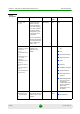
The following table lists the pin numbers of the 25-pin micro D-Type
ALRM-IN/OUT connector corresponding to the alarm number you are configuring:
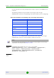
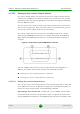
Refer Figure 3-2
for a diagrammatic representation of the 25-pin micro D-Type
ALRM-IN/OUT connector and the numbers assigned to each pin.
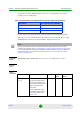
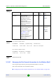
Table 3-28: Pin Numbers Corresponding to Dry Contact Input Alarm Numbers
Pin Number Alarm Number
3 and 15 1
4 and 16 2
5 and 17 3
6 and 18 4
7 and 19 5
8 and 20 6
9 and 21 7
10 and 22 8
NOTE
For more information about displaying the alarm conditions currently mapped to the micro D-Type
ALRM-IN/OUT connector pins, refer
Section 3.3.15.6.
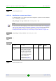
Command
Syntax
npu(config)# dry-contact IN <alarm_num (1-8)> alarm
{CommercialPowerFailure | Fire | EnclosueDoorOpen | HighTemperature |
Flood | LowFuel | LowBatteryThreshold | GeneratorFailure |
IntrusionDetection | ExternalEquipmentFailure} [alarmPolarity
{RaiseOnClose | RaiseOnOpen }]
Privilege
Level
10