
User's Manual
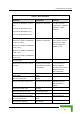
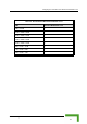
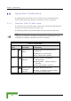
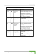
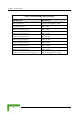
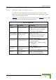
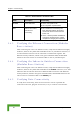
Table Of Contents
- BreezeACCESS 4900 System Manual
- About This Manual
- Contents
- Figures
- Tables
- Chapter 1 - System Description
- Chapter 2 - Installation
- Chapter 3 - Commissioning
- Chapter 4 - Operation and Administration
- Working with the Monitor Program
- Menus and Parameters
- Main Menu
- Info Screens Menu
- Unit Control Menu
- Basic Configuration Menu
- Site Survey Menu
- Advanced Configuration Menu
- IP Parameters
- Air Interface Parameters
- ESSID Parameters
- Frequency Definition Parameters
- Frequency Definition Submenu in AU
- Frequency Definition Submenu in SU
- Best AU Parameters (SU)
- Scanning Mode (SU only)
- Power Control Parameters
- Antenna Gain
- Cell Distance Parameters (AU only)
- Arbitration Inter-Frame Spacing (AIFS)
- Maximum Number of Associations (AU only)
- Wireless Link Trap Threshold (AU only)
- Spectrum Analysis
- Lost Beacons Transmission Watchdog Threshold
- Disassociate (AU only)
- Network Management Parameters
- Bridge Parameters
- VLAN Support
- Ethernet Broadcast Filtering (SU only)
- Ethernet Broadcast/Multicast Limiter
- Bridge Aging Time
- Broadcast Relaying (AU only)
- Unicast Relaying (AU only)
- MAC Address Deny List (AU only)
- Add MAC Address to Deny List
- Remove MAC Address from Deny List
- Roaming Option (SU only)
- Ports Control (SU only)
- Show Bridge Parameters
- Performance Parameters
- Service Parameters
- Security Parameters
- Appendix A - Software Version Loading Using TFTP
- Appendix B - File Download and Upload Using TFTP
- Appendix C - Using the Set Factory Defaults Utility
- Appendix D - Preparing the Indoor to Outdoor SU Cable
- Appendix E - Supported MIBS and Traps
- Appendix F - Parameters Summary
- Appendix G - Using the Feature License Web Application
- Appendix H - Troubleshooting

Chapter 3 - Commissioning
Table 3-7: PS1073 SU IDU / AU-SA IDU LEDs
Na me Description Functionality
POWER Powe
Green - IDU power is OK
r Indication
Off - No power or power failure
ETH
been detected between the outdoor
unit and the device connected to the
Self test and end-to-
end Ethernet
Off - No Ethernet connectivity has
connectivity
indoor unit.
Green - Self-test passed and Ethernet
connection confirmed by the outdoor
unit (Ethernet integrity check passed).
3.4.3 Verifying the Ethernet Connection (Modular
Base station)
necting the unit to an Ethe , verify that the Ethernet Integrity
ator, which is the yellow LED e ed in the 10/100 BaseT connector, is
on. This indicates that the unit is connected to an Ethernet segment. The
hernet Activity Indicator, which is green embedded LED, should blink
whenever the unit receives or transmits traffic on the 10/100 BaseT port.
.4.4 Verifying the Indoor-to-Outdoor Connection
Modular Base Station)
y
his
indicates that the unit has detected an Ethernet link connection. The Ethernet
t
un
3.4.5 Verifying Data Connectivity
To verify data connectivity, from the end-user’s PC or from a portable PC
connected to the unit, ping the Access Unit, or try to connect to the Internet.
After con rnet outlet
Indic mbedd
Et the
3
(
After connecting the unit to an Ethernet outlet, verify that the Ethernet Integrit
Indicator, which is the yellow LED embedded in the RADIO connector, is on. T
Ac ivity Indicator, which is the green embedded LED, should blink whenever the
it receives or transmits traffic on the RADIO port.
BreezeACCESS 4900 System Manual
52