
User's Manual
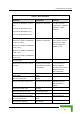
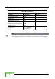
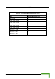
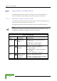
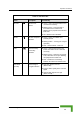
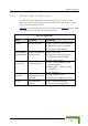
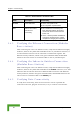
Table Of Contents
- BreezeACCESS 4900 System Manual
- About This Manual
- Contents
- Figures
- Tables
- Chapter 1 - System Description
- Chapter 2 - Installation
- Chapter 3 - Commissioning
- Chapter 4 - Operation and Administration
- Working with the Monitor Program
- Menus and Parameters
- Main Menu
- Info Screens Menu
- Unit Control Menu
- Basic Configuration Menu
- Site Survey Menu
- Advanced Configuration Menu
- IP Parameters
- Air Interface Parameters
- ESSID Parameters
- Frequency Definition Parameters
- Frequency Definition Submenu in AU
- Frequency Definition Submenu in SU
- Best AU Parameters (SU)
- Scanning Mode (SU only)
- Power Control Parameters
- Antenna Gain
- Cell Distance Parameters (AU only)
- Arbitration Inter-Frame Spacing (AIFS)
- Maximum Number of Associations (AU only)
- Wireless Link Trap Threshold (AU only)
- Spectrum Analysis
- Lost Beacons Transmission Watchdog Threshold
- Disassociate (AU only)
- Network Management Parameters
- Bridge Parameters
- VLAN Support
- Ethernet Broadcast Filtering (SU only)
- Ethernet Broadcast/Multicast Limiter
- Bridge Aging Time
- Broadcast Relaying (AU only)
- Unicast Relaying (AU only)
- MAC Address Deny List (AU only)
- Add MAC Address to Deny List
- Remove MAC Address from Deny List
- Roaming Option (SU only)
- Ports Control (SU only)
- Show Bridge Parameters
- Performance Parameters
- Service Parameters
- Security Parameters
- Appendix A - Software Version Loading Using TFTP
- Appendix B - File Download and Upload Using TFTP
- Appendix C - Using the Set Factory Defaults Utility
- Appendix D - Preparing the Indoor to Outdoor SU Cable
- Appendix E - Supported MIBS and Traps
- Appendix F - Parameters Summary
- Appendix G - Using the Feature License Web Application
- Appendix H - Troubleshooting

Chapter 3 - Commissioning
3.4 Operation Verification
ing sections describe how t rect functioning of the
nit, Indoor Unit, Ethernet c vity.
3.4.1 r Unit Verifica
operation of the Outdoor Unit, examine the LED indicators
l of the ou
The following tables list the provided LEDs and their associated indications.
The follow o verify the cor
Outdoor U onnection and data connecti
Outdoo tion
To verify the correct
located on the bottom pane tdoor unit.
NOTE
Verifying the correct operation of the Outdoor Unit using the LEDs, as described below, is only
possible after the configuration and alignment ompleted. processes are c
Table 3-3: AU-O
DU LEDs
Name Description Functionality
W-LINK
Wireless Link
Indictor
Green – Unit is associated with one or
more SUs
Blinking red – No associations
Off – Wireless link is disabled
Status Self-test and power
indication
Green – Power is available and
self-test passed.
Blinking Amber – Testing (not ready for
operation)
Red – Self-test failed – fatal error
ETH Ethernet activity/
connectivity
indication
Green –Ethernet link detected.
Amber – No Ethernet connectivity between
the indoor and outdoor units.
BreezeACCESS 4900 System Manual
48