
User's Manual
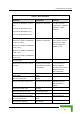
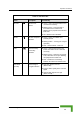
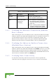
Table Of Contents
- BreezeACCESS 4900 System Manual
- About This Manual
- Contents
- Figures
- Tables
- Chapter 1 - System Description
- Chapter 2 - Installation
- Chapter 3 - Commissioning
- Chapter 4 - Operation and Administration
- Working with the Monitor Program
- Menus and Parameters
- Main Menu
- Info Screens Menu
- Unit Control Menu
- Basic Configuration Menu
- Site Survey Menu
- Advanced Configuration Menu
- IP Parameters
- Air Interface Parameters
- ESSID Parameters
- Frequency Definition Parameters
- Frequency Definition Submenu in AU
- Frequency Definition Submenu in SU
- Best AU Parameters (SU)
- Scanning Mode (SU only)
- Power Control Parameters
- Antenna Gain
- Cell Distance Parameters (AU only)
- Arbitration Inter-Frame Spacing (AIFS)
- Maximum Number of Associations (AU only)
- Wireless Link Trap Threshold (AU only)
- Spectrum Analysis
- Lost Beacons Transmission Watchdog Threshold
- Disassociate (AU only)
- Network Management Parameters
- Bridge Parameters
- VLAN Support
- Ethernet Broadcast Filtering (SU only)
- Ethernet Broadcast/Multicast Limiter
- Bridge Aging Time
- Broadcast Relaying (AU only)
- Unicast Relaying (AU only)
- MAC Address Deny List (AU only)
- Add MAC Address to Deny List
- Remove MAC Address from Deny List
- Roaming Option (SU only)
- Ports Control (SU only)
- Show Bridge Parameters
- Performance Parameters
- Service Parameters
- Security Parameters
- Appendix A - Software Version Loading Using TFTP
- Appendix B - File Download and Upload Using TFTP
- Appendix C - Using the Set Factory Defaults Utility
- Appendix D - Preparing the Indoor to Outdoor SU Cable
- Appendix E - Supported MIBS and Traps
- Appendix F - Parameters Summary
- Appendix G - Using the Feature License Web Application
- Appendix H - Troubleshooting

Chapter 3 - Commissioning
3.3 Configuring the Subscriber Unit’s
Maximum Modulation Level
or This section describes how to configure the maximum modulation level f
Subscriber Units.
NOTE
If the unit is associated with the AU, then the final configuration of the Maximum Modulation Level
parameter may be performed remotely, for example, from the site of the AU or from another site.
To configure the Maximum Modulation Level:
value that is lower
than the maximum supported by the unit. This can decrease the number of
r transmissions due to attempts to transmit at modulation levels that are too
high for the actua
2 Check the SNR of the SU at the AU. You can use Telnet to view the SNR
values in dress D h can be accessed from the Site
Survey m TPC al he
test sho ne with the In Level at the SU configured to its
maximum value. If the SNR d for the
maximum modulation level ac ommended that
you decrease the value of the
1 If the SNR of the SU at the AU is too low, it is recommended that you
configure the Maximum Modulation Level parameter to a
e
l quality of the link.
the MAC Ad atabase, whic
enu. If the A
uld be do
gorithm is not enabled in both AU and SU, t
itial Power
is lower than the values require
cording to Table 3-2, it is rec
Maximum Modulation Level.
NOTE
The SNR measurement at the AU is ac e curate only when receiving transmissions from th
applicable SU. If necessary, use the Ping T he Site Survey menu to verify data est utility in t
transmission.
3 Configure the Maximum Modulat 3-2, using the
typical S eco added to
compens ible mea ality of
the link.
ion Level according to Table
mmended that a 2 dB margin beNR values. It is r
ate for poss
surement inaccuracy or variance in the qu
BreezeACCESS 4900 System Manual
46