
User's Manual
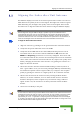
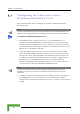
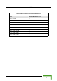
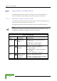
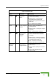
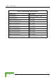
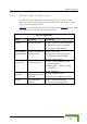
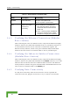
Table Of Contents
- BreezeACCESS 4900 System Manual
- About This Manual
- Contents
- Figures
- Tables
- Chapter 1 - System Description
- Chapter 2 - Installation
- Chapter 3 - Commissioning
- Chapter 4 - Operation and Administration
- Working with the Monitor Program
- Menus and Parameters
- Main Menu
- Info Screens Menu
- Unit Control Menu
- Basic Configuration Menu
- Site Survey Menu
- Advanced Configuration Menu
- IP Parameters
- Air Interface Parameters
- ESSID Parameters
- Frequency Definition Parameters
- Frequency Definition Submenu in AU
- Frequency Definition Submenu in SU
- Best AU Parameters (SU)
- Scanning Mode (SU only)
- Power Control Parameters
- Antenna Gain
- Cell Distance Parameters (AU only)
- Arbitration Inter-Frame Spacing (AIFS)
- Maximum Number of Associations (AU only)
- Wireless Link Trap Threshold (AU only)
- Spectrum Analysis
- Lost Beacons Transmission Watchdog Threshold
- Disassociate (AU only)
- Network Management Parameters
- Bridge Parameters
- VLAN Support
- Ethernet Broadcast Filtering (SU only)
- Ethernet Broadcast/Multicast Limiter
- Bridge Aging Time
- Broadcast Relaying (AU only)
- Unicast Relaying (AU only)
- MAC Address Deny List (AU only)
- Add MAC Address to Deny List
- Remove MAC Address from Deny List
- Roaming Option (SU only)
- Ports Control (SU only)
- Show Bridge Parameters
- Performance Parameters
- Service Parameters
- Security Parameters
- Appendix A - Software Version Loading Using TFTP
- Appendix B - File Download and Upload Using TFTP
- Appendix C - Using the Set Factory Defaults Utility
- Appendix D - Preparing the Indoor to Outdoor SU Cable
- Appendix E - Supported MIBS and Traps
- Appendix F - Parameters Summary
- Appendix G - Using the Feature License Web Application
- Appendix H - Troubleshooting

Aligning the Subscriber Unit Antenna
3.2 ligning the Subscriber Unit Antenna
The SNR bar display is located on the bottom panel of the outdoor unit. The ten
LEDs indicate the quality of the re e number of green
LEDs indicating On, the higher the quality of the received signal. This section
es how to align the Subscriber Unit antenna using the SNR bar display.
A
ceived signal. The higher th
describ
NOTE
Antenna alignment using the SNR bar dis y is possible only after the Subscriber Unit is pla
associated with an Access Unit. The associ ccess Unit must be operational and the basic ated A
Subscriber Unit parameters must be corre y configured. Otherwise, the unit will not be able to ctl
synchronize with the Access Unit. As the R measurement is performed on received frames, its SN
results are meaningless unless the Subscri it is associated with an Access Unit. ber Un
To align the Subscriber Unit antenna:
antenna by pointing it in the general direction of the Base Station.
at the power indicatio f the unit is On.
3 Verify that the W-LINK LED of the ODU is On, indicating that the unit is
associated with an Access Unit. If the W-LINK LED is Off, check that the
ESSID and Frequency parameters are correctly configured. If the SU is still
not associated with the AU, increase the transmit power level to its maximum
value. If the unit is still not associated with the AU, improve the quality of the
link by changing the direction of the antenna or by placing the antenna at a
higher or alternate location.
4 Rotate the antenna until the maximum SNR reading is achieved, where at
least 1 green LED is on. If you encounter prolonged difficulty in illuminating
the minimum required number of green LEDs, try to improve the reception
quality by placing the antenna at a higher point or in an alternate location.
5 Ensure that the front of the antenna is always facing the Base Station.
However, in certain conditions, such as when the line of site to the Base
Station is hampered, better reception may be achieved using a reflected
signal. In this case, the antenna is not always directed toward the Base
Station.
6 Secure the unit firmly to the pole.
1 Align the
2 Verify th n o
NOTE
In some cases, the antenna may need to be tilted to ensure that the level at which the SU receives
transmissions from the AU (and vice versa) is not too high. As a rule of thumb, if the SU is located
at a distance of less than 300 meters from the AU, it is recommended to up-tilt the antenna by
approximately 10° to 15°. To guarantee a safety margin from the saturation level (received signal
of –40 dBm at the antenna port), the SNR should not be higher than 50 dB. The orange LED of the
SNR bar indicates that the SNR is higher than 50 dB.
Commissioning
45