
User's Manual
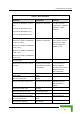
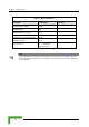
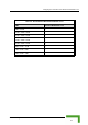
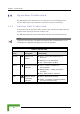
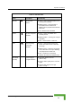
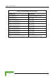
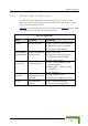
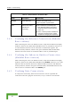
Table Of Contents
- BreezeACCESS 4900 System Manual
- About This Manual
- Contents
- Figures
- Tables
- Chapter 1 - System Description
- Chapter 2 - Installation
- Chapter 3 - Commissioning
- Chapter 4 - Operation and Administration
- Working with the Monitor Program
- Menus and Parameters
- Main Menu
- Info Screens Menu
- Unit Control Menu
- Basic Configuration Menu
- Site Survey Menu
- Advanced Configuration Menu
- IP Parameters
- Air Interface Parameters
- ESSID Parameters
- Frequency Definition Parameters
- Frequency Definition Submenu in AU
- Frequency Definition Submenu in SU
- Best AU Parameters (SU)
- Scanning Mode (SU only)
- Power Control Parameters
- Antenna Gain
- Cell Distance Parameters (AU only)
- Arbitration Inter-Frame Spacing (AIFS)
- Maximum Number of Associations (AU only)
- Wireless Link Trap Threshold (AU only)
- Spectrum Analysis
- Lost Beacons Transmission Watchdog Threshold
- Disassociate (AU only)
- Network Management Parameters
- Bridge Parameters
- VLAN Support
- Ethernet Broadcast Filtering (SU only)
- Ethernet Broadcast/Multicast Limiter
- Bridge Aging Time
- Broadcast Relaying (AU only)
- Unicast Relaying (AU only)
- MAC Address Deny List (AU only)
- Add MAC Address to Deny List
- Remove MAC Address from Deny List
- Roaming Option (SU only)
- Ports Control (SU only)
- Show Bridge Parameters
- Performance Parameters
- Service Parameters
- Security Parameters
- Appendix A - Software Version Loading Using TFTP
- Appendix B - File Download and Upload Using TFTP
- Appendix C - Using the Set Factory Defaults Utility
- Appendix D - Preparing the Indoor to Outdoor SU Cable
- Appendix E - Supported MIBS and Traps
- Appendix F - Parameters Summary
- Appendix G - Using the Feature License Web Application
- Appendix H - Troubleshooting

Configuring Basic Parameters
Table 3-1: Basic Parameters
Parameter Default Value Comment
Tx Powe
to 5,
Tx Power for Modulation Level 6,
Tx Power for n Level 7,
Tx Powe
parameter.
r for Modulation Levels 1
Dependent on Sub-Band Tx Power cannot be
higher than the applicable
Maximum Tx Power
Modulatio
r for Modulation Level 8
Maximum Tx Power for Modulation
evels 1
Maximu
Level 6 (SU),
Maximum Tx Power for Modulation
Level 7
Maximum T
Level 8 (SU
n Sub-Band
Max Tx Power cannot be
higher than the upper
L to 5 (SU),
Dependent o
m Tx Power for Modulation
limit according to the
Sub-Band in use.
(SU)
x Power for Modulation
)
Tx Power (AU) On
Antenna Gai
antenna
ing to the antenna
If set to “Not Set Yet”,
n (units with external Accord
) supplied with the unit and
the Sub-Band.
must be configured
according to actual value,
taking into account
cable’s attenuation.
ATPC Option Enable
Best AU Support (SU) Disable
Preferred A
Best AU Support is
enabled.
U MAC Address (SU) 00-00-00-00-00-00 (none) Applicable only when
Cell Distance Mode (AU) Automatic
Maximum Cell Distance (AU) 0 (No Compensation)
Maximum Modulation Level (SU) 8 Refer to section 3.3.
VLAN ID-Management 65535
Authentication Algorithm Open System
Commissioning
43