
User's Manual
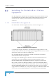
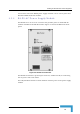
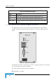
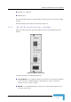


Table Of Contents
- BreezeACCESS 4900 System Manual
- About This Manual
- Contents
- Figures
- Tables
- Chapter 1 - System Description
- Chapter 2 - Installation
- Chapter 3 - Commissioning
- Chapter 4 - Operation and Administration
- Working with the Monitor Program
- Menus and Parameters
- Main Menu
- Info Screens Menu
- Unit Control Menu
- Basic Configuration Menu
- Site Survey Menu
- Advanced Configuration Menu
- IP Parameters
- Air Interface Parameters
- ESSID Parameters
- Frequency Definition Parameters
- Frequency Definition Submenu in AU
- Frequency Definition Submenu in SU
- Best AU Parameters (SU)
- Scanning Mode (SU only)
- Power Control Parameters
- Antenna Gain
- Cell Distance Parameters (AU only)
- Arbitration Inter-Frame Spacing (AIFS)
- Maximum Number of Associations (AU only)
- Wireless Link Trap Threshold (AU only)
- Spectrum Analysis
- Lost Beacons Transmission Watchdog Threshold
- Disassociate (AU only)
- Network Management Parameters
- Bridge Parameters
- VLAN Support
- Ethernet Broadcast Filtering (SU only)
- Ethernet Broadcast/Multicast Limiter
- Bridge Aging Time
- Broadcast Relaying (AU only)
- Unicast Relaying (AU only)
- MAC Address Deny List (AU only)
- Add MAC Address to Deny List
- Remove MAC Address from Deny List
- Roaming Option (SU only)
- Ports Control (SU only)
- Show Bridge Parameters
- Performance Parameters
- Service Parameters
- Security Parameters
- Appendix A - Software Version Loading Using TFTP
- Appendix B - File Download and Upload Using TFTP
- Appendix C - Using the Set Factory Defaults Utility
- Appendix D - Preparing the Indoor to Outdoor SU Cable
- Appendix E - Supported MIBS and Traps
- Appendix F - Parameters Summary
- Appendix G - Using the Feature License Web Application
- Appendix H - Troubleshooting

Installing the Modular Base Station Equipment
9 If a BS-PS-AC power supply is used, connect the AC power cord to the AC IN
jack of the BS-PS-AC power supply. If a redundant power supply mo
installed, connect an AC power cord also to the second AC power mo
Connect the power cord(s) to the mains outlet.
10 Switch the BS-PS-AC/DC power supplies to ON. Verify that all powe
indicator LEDs on the BS-PS-AC/DC front panel are ON and that th
OVERTEMP alarm indicator is off. Refer to Table 2-2 for a descriptio
LEDs.
11 Configure the basic parameters in all BS-AU modules as described in section
3.1
dule is
dule.
r
e
n of these
.
r(s) to the network. The cable
connecting the indoor unit to a
hub/switch and a crossed cable if connecting it directly to a PC Network
Interface Card (NIC).
12 Connect the 10/100 BaseT LAN connecto
connection should be straight Ethernet if
NOTE
The length of each of the Ethernet cables (the cable connecting the indoor unit to the user's
equipment and the Indoor-to-Outdoor cable) should not exceed 100 meters.
Reset the unit using the RESET button after connecting or reconnecting the indoor and outdoor
units with the indoor-to-outdoor cable.
Installation
39