
User's Manual
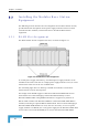
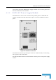
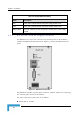
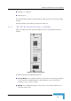


Table Of Contents
- BreezeACCESS 4900 System Manual
- About This Manual
- Contents
- Figures
- Tables
- Chapter 1 - System Description
- Chapter 2 - Installation
- Chapter 3 - Commissioning
- Chapter 4 - Operation and Administration
- Working with the Monitor Program
- Menus and Parameters
- Main Menu
- Info Screens Menu
- Unit Control Menu
- Basic Configuration Menu
- Site Survey Menu
- Advanced Configuration Menu
- IP Parameters
- Air Interface Parameters
- ESSID Parameters
- Frequency Definition Parameters
- Frequency Definition Submenu in AU
- Frequency Definition Submenu in SU
- Best AU Parameters (SU)
- Scanning Mode (SU only)
- Power Control Parameters
- Antenna Gain
- Cell Distance Parameters (AU only)
- Arbitration Inter-Frame Spacing (AIFS)
- Maximum Number of Associations (AU only)
- Wireless Link Trap Threshold (AU only)
- Spectrum Analysis
- Lost Beacons Transmission Watchdog Threshold
- Disassociate (AU only)
- Network Management Parameters
- Bridge Parameters
- VLAN Support
- Ethernet Broadcast Filtering (SU only)
- Ethernet Broadcast/Multicast Limiter
- Bridge Aging Time
- Broadcast Relaying (AU only)
- Unicast Relaying (AU only)
- MAC Address Deny List (AU only)
- Add MAC Address to Deny List
- Remove MAC Address from Deny List
- Roaming Option (SU only)
- Ports Control (SU only)
- Show Bridge Parameters
- Performance Parameters
- Service Parameters
- Security Parameters
- Appendix A - Software Version Loading Using TFTP
- Appendix B - File Download and Upload Using TFTP
- Appendix C - Using the Set Factory Defaults Utility
- Appendix D - Preparing the Indoor to Outdoor SU Cable
- Appendix E - Supported MIBS and Traps
- Appendix F - Parameters Summary
- Appendix G - Using the Feature License Web Application
- Appendix H - Troubleshooting

Chapter 2 - Installation
CAUTION
Do not connect the data equipment to the RADIO port. The RADIO port supplies DC power to the
ODU, and this may harm other equipment connected to it.
The recessed RESET switch on the front panel is for resetting the outdoor unit.
2.5.5 Installing the BS-SH Chassis and Modules
This section describes how to install the power supply and Access Unit network
interface modules in the Base Station chassis.
To install the BS SH chassis and modules:
1 Install the BS-SH chassis in a 19” cabinet. To prevent over-heating, leave a
free space of at least 1U between the upper/lower covers of the BS-SH chassis
and other units in the cabinet.
OR
Place the BS-SH chassis on an appropriate shelf or table. When mounting the
BS-SH on a shelf or table, attach the rubber legs supplied with the unit.
2 Connect one end of a grounding cable to the ground terminal located on the
rear panel of the BS-SH chassis and firmly tighten the grounding screw.
3 Connect the opposite end of the grounding cable to a ground connection or to
the cabinet, if applicable.
4 Carefully insert the BS-PS power supply and the BS-AU modules into the
relevant slots and push firmly until they are securely locked. Before insertion,
verify that the switches of all BS-PS modules are in the OFF position. Refer to
section 2.5.1
for a description of the slot assignment.
5 Close the captive screws attached to each module.
6 Place blank covers over all of the unused slots.
7 Connect the indoor-to outdoor cable(s) to the RADIO connector(s) of the
BS-AU module(s).
8 If a BS-PS-DC power supply is used, connect the DC power cord to the -48
VDC IN jack of the BS-PS-DC power supply. If a redundant power supply
module is installed, connect a DC power cord also to the second DC power
module. Connect the power cord(s) to the -48 VDC power source, as follows:
a Connect the black wire to the 48 VDC contact of the power source.
b Connect the red wire to the + (Return) contact.
c Connect the shield to the ground.
BreezeACCESS 4900 System Manual
38