
User's Manual
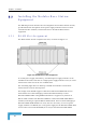
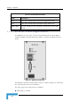


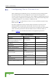
Table Of Contents
- BreezeACCESS 4900 System Manual
- About This Manual
- Contents
- Figures
- Tables
- Chapter 1 - System Description
- Chapter 2 - Installation
- Chapter 3 - Commissioning
- Chapter 4 - Operation and Administration
- Working with the Monitor Program
- Menus and Parameters
- Main Menu
- Info Screens Menu
- Unit Control Menu
- Basic Configuration Menu
- Site Survey Menu
- Advanced Configuration Menu
- IP Parameters
- Air Interface Parameters
- ESSID Parameters
- Frequency Definition Parameters
- Frequency Definition Submenu in AU
- Frequency Definition Submenu in SU
- Best AU Parameters (SU)
- Scanning Mode (SU only)
- Power Control Parameters
- Antenna Gain
- Cell Distance Parameters (AU only)
- Arbitration Inter-Frame Spacing (AIFS)
- Maximum Number of Associations (AU only)
- Wireless Link Trap Threshold (AU only)
- Spectrum Analysis
- Lost Beacons Transmission Watchdog Threshold
- Disassociate (AU only)
- Network Management Parameters
- Bridge Parameters
- VLAN Support
- Ethernet Broadcast Filtering (SU only)
- Ethernet Broadcast/Multicast Limiter
- Bridge Aging Time
- Broadcast Relaying (AU only)
- Unicast Relaying (AU only)
- MAC Address Deny List (AU only)
- Add MAC Address to Deny List
- Remove MAC Address from Deny List
- Roaming Option (SU only)
- Ports Control (SU only)
- Show Bridge Parameters
- Performance Parameters
- Service Parameters
- Security Parameters
- Appendix A - Software Version Loading Using TFTP
- Appendix B - File Download and Upload Using TFTP
- Appendix C - Using the Set Factory Defaults Utility
- Appendix D - Preparing the Indoor to Outdoor SU Cable
- Appendix E - Supported MIBS and Traps
- Appendix F - Parameters Summary
- Appendix G - Using the Feature License Web Application
- Appendix H - Troubleshooting

Chapter 2 - Installation
Table 2-2: BS-PS LED Functionality
Name Description
54V es that the 54V power supply module is OK Green LED. Indicat
3.3V Green LED. Indicates that the 3.3V power supply module is OK
OVER Red LED. Indicates an over temperature condition in the power supply TEMP
module
2.5.3
BS-PS-DC Power Supply Module
The BS-PS-DC is a DC-to-DC converter that provides power to all the BS-AU
modules installed in the BS-SH chassis. Figure 2-7 shows the BS-PS-DC front
panel.
Figure 2-7: BS-PS-DC Front Panel
Th BS-PS-DC provides a power input connector, marked -48VDC, for connect
-48 VDC power sou
e ing
the rce to the module.
e
Black (pin 2): 48 VDC
Th color codes of the cable wires are as follows:
BreezeACCESS 4900 System Manual
36