
User's Manual
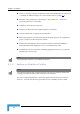
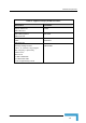
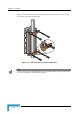
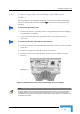
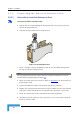
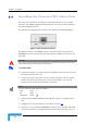
Table Of Contents
- BreezeACCESS 4900 System Manual
- About This Manual
- Contents
- Figures
- Tables
- Chapter 1 - System Description
- Chapter 2 - Installation
- Chapter 3 - Commissioning
- Chapter 4 - Operation and Administration
- Working with the Monitor Program
- Menus and Parameters
- Main Menu
- Info Screens Menu
- Unit Control Menu
- Basic Configuration Menu
- Site Survey Menu
- Advanced Configuration Menu
- IP Parameters
- Air Interface Parameters
- ESSID Parameters
- Frequency Definition Parameters
- Frequency Definition Submenu in AU
- Frequency Definition Submenu in SU
- Best AU Parameters (SU)
- Scanning Mode (SU only)
- Power Control Parameters
- Antenna Gain
- Cell Distance Parameters (AU only)
- Arbitration Inter-Frame Spacing (AIFS)
- Maximum Number of Associations (AU only)
- Wireless Link Trap Threshold (AU only)
- Spectrum Analysis
- Lost Beacons Transmission Watchdog Threshold
- Disassociate (AU only)
- Network Management Parameters
- Bridge Parameters
- VLAN Support
- Ethernet Broadcast Filtering (SU only)
- Ethernet Broadcast/Multicast Limiter
- Bridge Aging Time
- Broadcast Relaying (AU only)
- Unicast Relaying (AU only)
- MAC Address Deny List (AU only)
- Add MAC Address to Deny List
- Remove MAC Address from Deny List
- Roaming Option (SU only)
- Ports Control (SU only)
- Show Bridge Parameters
- Performance Parameters
- Service Parameters
- Security Parameters
- Appendix A - Software Version Loading Using TFTP
- Appendix B - File Download and Upload Using TFTP
- Appendix C - Using the Set Factory Defaults Utility
- Appendix D - Preparing the Indoor to Outdoor SU Cable
- Appendix E - Supported MIBS and Traps
- Appendix F - Parameters Summary
- Appendix G - Using the Feature License Web Application
- Appendix H - Troubleshooting

Chapter 2 - Installation
2.4 Installing the Universal IDU Indoor Unit
used to facilitate
n in the following figure:
The unit can be placed on a desktop or a shelf. Alternatively, it may be wall-
mounted. The drilling template included with the unit can be
the wall installation process.
The equipment is shipped with a PS1073 IDU, show
Figure 2-4: IDU PS 1073 Front Panel
The RADIO connector and RESET button are located on the front panel, the
ETHERNET connector is located on the side panel and LEDs are located on the
top panel.
CAUTION
Do not connect the data equipment to the RADIO port. The RADIO port supplies DC power to the
ODU, and this may harm other equipment connected to it.
To install the IDU:
1 Connect the Indoor-to-Outdoor cable to the RADIO connector, located on the
front panel of the indoor unit.
2 Connect the power cord to the unit's AC socket, located on the rear panel.
Connect the other end of the power cord to the AC mains. The unit can
operate with AC mains of 100-240 VAC, 50-60 Hz.
NOTE
The color codes of the power cable are as follows:
Brown Phase ~
Blue Neutral 0
Yellow/Green Ground
3 Verify that the POWER LED is lit, indicating that power is supplied to the
unit.
4 Configure the basic parameters as described in section 3.1
.
5 Connect the 10/100 BaseT ETHERNET connector to the network. The cable
connection should be a straight Ethernet if connecting the indoor unit to a
BreezeACCESS 4900 System Manual
32