
User's Manual
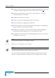
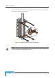
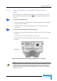
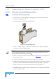
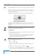
Table Of Contents
- BreezeACCESS 4900 System Manual
- About This Manual
- Contents
- Figures
- Tables
- Chapter 1 - System Description
- Chapter 2 - Installation
- Chapter 3 - Commissioning
- Chapter 4 - Operation and Administration
- Working with the Monitor Program
- Menus and Parameters
- Main Menu
- Info Screens Menu
- Unit Control Menu
- Basic Configuration Menu
- Site Survey Menu
- Advanced Configuration Menu
- IP Parameters
- Air Interface Parameters
- ESSID Parameters
- Frequency Definition Parameters
- Frequency Definition Submenu in AU
- Frequency Definition Submenu in SU
- Best AU Parameters (SU)
- Scanning Mode (SU only)
- Power Control Parameters
- Antenna Gain
- Cell Distance Parameters (AU only)
- Arbitration Inter-Frame Spacing (AIFS)
- Maximum Number of Associations (AU only)
- Wireless Link Trap Threshold (AU only)
- Spectrum Analysis
- Lost Beacons Transmission Watchdog Threshold
- Disassociate (AU only)
- Network Management Parameters
- Bridge Parameters
- VLAN Support
- Ethernet Broadcast Filtering (SU only)
- Ethernet Broadcast/Multicast Limiter
- Bridge Aging Time
- Broadcast Relaying (AU only)
- Unicast Relaying (AU only)
- MAC Address Deny List (AU only)
- Add MAC Address to Deny List
- Remove MAC Address from Deny List
- Roaming Option (SU only)
- Ports Control (SU only)
- Show Bridge Parameters
- Performance Parameters
- Service Parameters
- Security Parameters
- Appendix A - Software Version Loading Using TFTP
- Appendix B - File Download and Upload Using TFTP
- Appendix C - Using the Set Factory Defaults Utility
- Appendix D - Preparing the Indoor to Outdoor SU Cable
- Appendix E - Supported MIBS and Traps
- Appendix F - Parameters Summary
- Appendix G - Using the Feature License Web Application
- Appendix H - Troubleshooting

Chapter 2 - Installation
2.3.3 Connecting the Indoor-to-Outdoor Cable
2.3.3.1 Units with an Installed Waterproof Seal
To connect the indoor-to-outdoor cable:
1 Remove the two screws holding the waterproof seal to the outdoor unit and
remove the waterproof seal.
2 Unscrew the top nut from the waterproof seal.
Figure 2-3: The Waterproof Seal
3 Route a straight Category 5E Ethernet cable (8-wire, 24 AWG) through both
the top nut and the waterproof seal.
NOTE
Use only Category 5E 4x2x24# FTP outdoor cables from an approved manufacturer. See list of
approved cables and length limitations in section 2.1.2.
4 Insert and crimp the RJ-45 connector. Refer to Appendix C for instructions on
preparing the cable.
5 Connect the Ethernet cable to the outdoor unit RJ-45 connector.
6 Replace the waterproof seal and then the top nut. Make sure that the external
tee a good seal. jack of the cable is well inside the waterproof seal to guaran
7 Route the cable to the location selected for the indoor equipment.
8 Assemble an RJ-45 connector with a protective cover on the indoor end of the
indoor-to-outdoor cable.
BreezeACCESS 4900 System Manual
30