
User's Manual
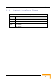
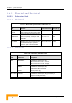
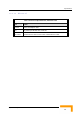
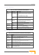
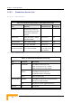

Table Of Contents
- BreezeACCESS 4900 System Manual
- About This Manual
- Contents
- Figures
- Tables
- Chapter 1 - System Description
- Chapter 2 - Installation
- Chapter 3 - Commissioning
- Chapter 4 - Operation and Administration
- Working with the Monitor Program
- Menus and Parameters
- Main Menu
- Info Screens Menu
- Unit Control Menu
- Basic Configuration Menu
- Site Survey Menu
- Advanced Configuration Menu
- IP Parameters
- Air Interface Parameters
- ESSID Parameters
- Frequency Definition Parameters
- Frequency Definition Submenu in AU
- Frequency Definition Submenu in SU
- Best AU Parameters (SU)
- Scanning Mode (SU only)
- Power Control Parameters
- Antenna Gain
- Cell Distance Parameters (AU only)
- Arbitration Inter-Frame Spacing (AIFS)
- Maximum Number of Associations (AU only)
- Wireless Link Trap Threshold (AU only)
- Spectrum Analysis
- Lost Beacons Transmission Watchdog Threshold
- Disassociate (AU only)
- Network Management Parameters
- Bridge Parameters
- VLAN Support
- Ethernet Broadcast Filtering (SU only)
- Ethernet Broadcast/Multicast Limiter
- Bridge Aging Time
- Broadcast Relaying (AU only)
- Unicast Relaying (AU only)
- MAC Address Deny List (AU only)
- Add MAC Address to Deny List
- Remove MAC Address from Deny List
- Roaming Option (SU only)
- Ports Control (SU only)
- Show Bridge Parameters
- Performance Parameters
- Service Parameters
- Security Parameters
- Appendix A - Software Version Loading Using TFTP
- Appendix B - File Download and Upload Using TFTP
- Appendix C - Using the Set Factory Defaults Utility
- Appendix D - Preparing the Indoor to Outdoor SU Cable
- Appendix E - Supported MIBS and Traps
- Appendix F - Parameters Summary
- Appendix G - Using the Feature License Web Application
- Appendix H - Troubleshooting

Specifications
1.6.5.2.2 Connectors
Table 1-11: Connectors, Modular Base Station Equipment
Unit Connector Description
10/100 BaseT 10/100BaseT Ethernet (RJ-45) with 2 embedded
LEDs.
Cable connection to a PC: crossed
Cable connection to a hub: straight
BS-AU
RADIO 10/100BaseT Ethernet (RJ-45) with 2 embedded
LEDs
INDOOR 10/100BaseT Ethernet (RJ-45), protected by a
waterproof sealing assembly
AU-D-BS-ODU
ANT N-Type jack, 50 ohm, lightning protected
BS-PS-AC AC-IN 3-PIN AC power plug
BS-PS-DC -48 VDC 3 pin DC D-Type 3 power pins plug
Amphenol 717TWA3W3PHP2V4RRM6
Antenna RF N-Type jack (on a 1.5m cable in the Omni-8-5.8)
1.6.5.2.3 Electrical
Table 1-12: Electrical Specifications, Modular Base Station Equipment
Unit Details
General 240W max. for a fully equipped chassis (1 PS, 6 AU)
BS-PS-AC AC power input: 85-265 VAC, 47-65 Hz
DC power output: 54 V; 3.3 V
BS-PS-DC DC power input: -48 VDC nominal (-34 to -72), 10 A max
DC power output: 54 V; 3.3 V
BS-AU 3.3 VDC, 54 VDC from the power supply module(s) via the back plane
AU-D-BS-ODU 54 VDC from the BS-AU over the indoor-outdoor Ethernet cable
AU-D-BS
(IDU+ODU)
Power consumption: 30W
System Description
17