
User's Manual
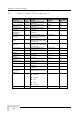

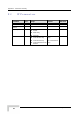
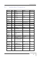
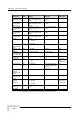
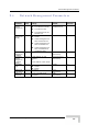
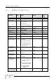

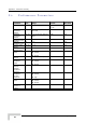
Table Of Contents
- BreezeACCESS 4900 System Manual
- About This Manual
- Contents
- Figures
- Tables
- Chapter 1 - System Description
- Chapter 2 - Installation
- Chapter 3 - Commissioning
- Chapter 4 - Operation and Administration
- Working with the Monitor Program
- Menus and Parameters
- Main Menu
- Info Screens Menu
- Unit Control Menu
- Basic Configuration Menu
- Site Survey Menu
- Advanced Configuration Menu
- IP Parameters
- Air Interface Parameters
- ESSID Parameters
- Frequency Definition Parameters
- Frequency Definition Submenu in AU
- Frequency Definition Submenu in SU
- Best AU Parameters (SU)
- Scanning Mode (SU only)
- Power Control Parameters
- Antenna Gain
- Cell Distance Parameters (AU only)
- Arbitration Inter-Frame Spacing (AIFS)
- Maximum Number of Associations (AU only)
- Wireless Link Trap Threshold (AU only)
- Spectrum Analysis
- Lost Beacons Transmission Watchdog Threshold
- Disassociate (AU only)
- Network Management Parameters
- Bridge Parameters
- VLAN Support
- Ethernet Broadcast Filtering (SU only)
- Ethernet Broadcast/Multicast Limiter
- Bridge Aging Time
- Broadcast Relaying (AU only)
- Unicast Relaying (AU only)
- MAC Address Deny List (AU only)
- Add MAC Address to Deny List
- Remove MAC Address from Deny List
- Roaming Option (SU only)
- Ports Control (SU only)
- Show Bridge Parameters
- Performance Parameters
- Service Parameters
- Security Parameters
- Appendix A - Software Version Loading Using TFTP
- Appendix B - File Download and Upload Using TFTP
- Appendix C - Using the Set Factory Defaults Utility
- Appendix D - Preparing the Indoor to Outdoor SU Cable
- Appendix E - Supported MIBS and Traps
- Appendix F - Parameters Summary
- Appendix G - Using the Feature License Web Application
- Appendix H - Troubleshooting

Appendix F - Parameters Summary
Parameter Unit Range Default Run-Time
Tx Power For
Modulation Level
AU, SU -10 dBm to a value
determined by the Sub-
B
The highest allowed
value
Yes
8 and
Max Tx Power
For Modulation
S -10 dBm to a value
determined by the Sub-
B
The highest allowed
value
Ye
Levels 1 to 5
U
and
s
Max Tx Po
For Modulatio
wer
n
S -
determined by the Sub-
Band
Th
value
Ye
Level 6
U 10 dBm to a value e highest allowed s
Max Tx Power
For Modulation
Level 7
SU -
d Sub-
B
The highest allowed
value
Yes 10 dBm to a value
etermined by the
and
Max Tx Power SU -
d
Band
he highest allowed
al
Yes
For Modulation
Level 8
10 dBm to a value
Sub-
T
vetermined by the ue
ATPC Option A
En YeU, SU
Disable
Enable
able s
Delta from
Minimum SNR
Level
AU 4-20
11 dB Yes (dB)
Minimum SNR
Level
A 4-60 (dB) 28 (dB) YeU s
Minimum
Interval Between
A 1 seconds) 30 (seconds) YeU -3600 ( s
ATPC Messages
ATPC Power
Level Steps
AU 1 4 Yes -20 (dB)
Tx Control AU
On Yes (unit is
reset
automatically)
Off
On
Antenna Gain AU,
SU***
0 – 50
AU: According to the
an ied with
the unit.
SU-E: NA
No (dB)
tenna suppl
Spectrum
Analysis
Channel Scan
Period
AU, SU 2 5 secon No – 30 seconds ds
Spectrum
Analysis Scan
Cycles
AU, SU 1 – 100 c 2 c No ycles ycles
Automatic AU
Disable
Enable
Disable No
(Co red
per analysis)
Channel
Selection
nfigu
Lost Beacons
Watchdog
Threshold
AU 1
Used
218 Yes 00 – 1000, 0 means Not
*** Configurable on gral antenna. ly in units without an inte
BreezeACCESS 4900 System Manual
218