
User's Manual
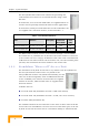

Table Of Contents
- BreezeACCESS 4900 System Manual
- About This Manual
- Contents
- Figures
- Tables
- Chapter 1 - System Description
- Chapter 2 - Installation
- Chapter 3 - Commissioning
- Chapter 4 - Operation and Administration
- Working with the Monitor Program
- Menus and Parameters
- Main Menu
- Info Screens Menu
- Unit Control Menu
- Basic Configuration Menu
- Site Survey Menu
- Advanced Configuration Menu
- IP Parameters
- Air Interface Parameters
- ESSID Parameters
- Frequency Definition Parameters
- Frequency Definition Submenu in AU
- Frequency Definition Submenu in SU
- Best AU Parameters (SU)
- Scanning Mode (SU only)
- Power Control Parameters
- Antenna Gain
- Cell Distance Parameters (AU only)
- Arbitration Inter-Frame Spacing (AIFS)
- Maximum Number of Associations (AU only)
- Wireless Link Trap Threshold (AU only)
- Spectrum Analysis
- Lost Beacons Transmission Watchdog Threshold
- Disassociate (AU only)
- Network Management Parameters
- Bridge Parameters
- VLAN Support
- Ethernet Broadcast Filtering (SU only)
- Ethernet Broadcast/Multicast Limiter
- Bridge Aging Time
- Broadcast Relaying (AU only)
- Unicast Relaying (AU only)
- MAC Address Deny List (AU only)
- Add MAC Address to Deny List
- Remove MAC Address from Deny List
- Roaming Option (SU only)
- Ports Control (SU only)
- Show Bridge Parameters
- Performance Parameters
- Service Parameters
- Security Parameters
- Appendix A - Software Version Loading Using TFTP
- Appendix B - File Download and Upload Using TFTP
- Appendix C - Using the Set Factory Defaults Utility
- Appendix D - Preparing the Indoor to Outdoor SU Cable
- Appendix E - Supported MIBS and Traps
- Appendix F - Parameters Summary
- Appendix G - Using the Feature License Web Application
- Appendix H - Troubleshooting

Base Station Equipment
1.2 Base Station Equipment
The Access Units, installed at the Base Station site, provide all the functionality
necessary to communicate with the Subscriber Units and to connect to the
backbone of the network.
There are 2 lines of Access Units with different architectures:
Modular Base Station Equipment
Standalone “Micro-Cell” Access Unit
1.2.1 Modular Base Station Equipment
The Base Station Equipment is based on the BS-SH 3U chassis, which is suitable
for installation in 19-inch racks. The chassis contains one or two Power Supply
modules and has 8 slots that can accommodate BS-AU Network Interface
modules. These slots can also
accommodate various combinations of
other modules, including Network
Interface (BS-AU) modules for Access
Units operating in any of the bands
supported by BreezeACCESS VL
equipment or BreezeACCESS equipment using GFSK modulation, including
BreezeACCESS 900, BreezeACCESS II, BreezeACCESS XL and BreezeACCESS V.
It can also accommodate a BS-GU GPS and Alarms module to support GPS-based
synchronization of BreezeACCESS systems using Frequency Hopping radios.
Two different types of power supply modules are available for the BreezeACCESS
4900 chassis: The BS-PS-DC that is powered from a -48 VDC power source, and
the BS-PS-AC, powered from the 110/220 VAC mains. The optional use of two
power supply modules ensures fail-safe operation through power supply
redundancy. When the same chassis is used also for Access Unit modules
belonging to other BreezeACCESS families using GFSK modulation, then one
BS-PS power supply (AC or DC) should be used to provide power to the
BreezeACCESS 4900 Access Units, and a different power supply module, suitable
for GFSK equipment, is required for powering the BreezeACCESS GFSK Access
Units.
Each BS-AU module, together with its outdoor AU-D/E-BS-ODU radio unit and
an antenna comprise an AU-D/E-BS Access Unit that serves a single sector/cell.
One AU-BS Access Unit can serve up to 512 Subscriber Units (124 when Data
Encryption is used).
System Description
3