
Installation Guide


WayPoint102 - 3 -
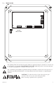
14. Place a jumper for non-latching output. A momentary short on these terminals resets output latching
[Trigger EOL Shutdown] (Fig. 1e, pg. 4).
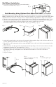
15. Upon completion of wiring secure enclosure door with latches and optional lock.
WARNING: When installing in a non-restricted service area use lock or other fastened means on door
latches. This installation should be made by qualified service personnel and should conform to the
National Electrical Code and all local codes.
LED Diagnostics:
Red (DC) Green (AC/AC1) Power Supply Status
ON ON Normal operating condition.
ON OFF Loss of AC. Stand-by battery supplying power.
OFF ON No DC output.
OFF OFF Loss of AC. Discharged or no stand-by battery. No DC output.
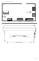
Terminal Identification:
Terminal
Legend
Function/Description
L, G, N
Connect 120VAC 60Hz to these terminals: L to hot, N to neutral(non power-limited)
(Fig. 1a, pg. 4).
– DC +
(Fig. 1h, pg. 4)
12VDC @ 10A continuous output (Non power-limited output).
Trigger EOL
Supervised
Trigger inputs can be normally open, normally closed from an output circuit
(power-limited input) (Fig. 1d, pg. 4).
NO, GND
RESET
Trigger input latching or non-latching (power-limited) (Fig. 1c, pg. 4).
+ AUX –
Auxiliary power-limited output rated @ 1A (unswitched) (power-limited output)
(Fig. 1f, pg. 4).
AC Fail
NC, C, NO
Indicates loss of AC power, e.g. connect to audible device or alarm panel.
Relay normally energized when AC power is present.
Contact rating 1A @ 30VDC (power-limited) (Fig. 1b, pg. 4).
Bat Fail
NC, C, NO
Indicates low battery condition, e.g. connect to alarm panel.
Relay normally energized when DC power is present. Contact rating 1A @ 30VDC.
A removed battery is reported within 5 minutes.
Battery reconnection is reported within 1 minute (power-limited) (Fig. 1b, pg. 4).
– BAT +
Stand-by battery connections. Maximum charge current 1.54A (non power-limited)
(Fig. 1g, pg. 4).