
Installation Instructions


Vertiline24C - 3 -
9. Upon completion of wiring, set illuminated master power disconnect circuit breaker to the
ON (RESET) position (F
ig. 3, pg. 6).
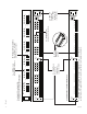
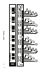
10. The power LEDs (Green) on the faceplate for Outputs 1-24 will illuminate when AC power is present
(F
ig. 1a, pg. 4). If any of these LEDs are off, a loss of AC power output may be due to a blown fuse or a tripped
PTC caused by a short circuit or overload condition. If all of the LEDs are OFF there may be a complete loss of
supply power to the Vertiline unit or the illuminated master power disconnect circuit breaker is in the OFF position
or the main fuse 1-12 or 13-24 is blown (Fig. 1c, pg. 4).*
To restore the power output for Vertiline24C or Vertiline246C:
1- Switch corresponding output voltage switch to the OFF position (Fig. 1b, pg. 4).
2-
Eliminate the trouble condition.
3- Replace the corresponding automotive blade fuse.*
4- Switch output voltage switch to the 24VAC or 28VAC position as desired (Fig. 1b, pg. 4).
To restore the power output for Vertiline24CD or Vertiline246CD:
1- Switch corresponding output voltage switch to the OFF position (Fig. 1b, pg. 4).
2-
Eliminate the trouble condition.
3- Allow 1 minute for PTC to cool off.
4- Switch output voltage switch to the 24VAC or 28VAC position as desired (Fig. 1b, pg. 4).
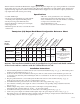
*Note: Replace fuses with same type and rating:
Output fuses are rated @ 3 amp for all models.
Main fuse ratings:
10 amp for
Vertiline24C and Vertiline24CD.
15 amp for Vertiline246C and Vertiline246CD.
Automotive
Blade Fuse