
Installation Instructions


- 2 - Vertiline8i/Vertiline16i
Overview:
Altronix Vertiline AC Isolated CCTV Rack Mount Power Supplies provide 8 or 16 camera channels in a space saving 1U
EIA 19” rack mount chassis which may be rack, wall or shelf mounted. The units feature individually selectable 24VAC
and/or 28VAC power outputs.
Specifications:
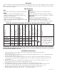
Eight (8) & Sixteen (16) Output Rack Mount Configuration Reference Chart:
Altronix
Model Number
Output
Voltage (VAC)
Total Output
Current (Power)
Number of Outputs
Output Protection
Class 2 Rated Power-
Limited Output Protection
Current (max. per output)
Fuse Rating
115VAC 60Hz Input
Current
230VAC 50/60Hz
Input Current
Agency Listings
UL Listings and
File Numbers
Vertiline8i
24VAC or
28VAC
8 amp 8
Fused -- 3 amp 3 amp
2.5
amp
1.5
amp
UL Listed for Commercial
CCTV Equipment (UL 2044).
CUL Listed - CSA Standard
C22.2 No.1-04,
Audio, Video and Similar
Equipment.
Vertiline8Di
24VAC or
28VAC
8 amp 8
-- PTC 2.5 amp --
Vertiline16i
24VAC or
28VAC
16 amp 16
Fused -- 3 amp 3 amp
5
amp
2.5
amp
Vertiline16Di
24VAC or
28VAC
16 amp 16
-- PTC 2.5 amp --
WARNING: To reduce the risk of fire or electric shock, do not expose the unit to rain or moisture.
This installation should be made by qualified service personnel and should conform to the National
Electrical Code and all local codes.
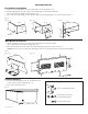
Installation Instructions:
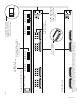
1. Set the input voltage selector switch located on the left side of the Vertiline unit for 115VAC or
230VAC operation (Fig. 1c, pg. 4).
2. Attach mounting brackets to Vertiline unit for rack or wall mount installation (Figs. 4-5, pg. 7). Affix rubber pads to
Vertiline for shelf installation (Fig. 6, pg. 7).
3. Secure the unit in a rack, mount unit to a wall or place unit on a shelf as desired (unit should be spaced at least
3” from any video monitors).When installing the unit in a rack, allow for one half of a U spacing above the unit
for ventilation.
4. Plug the grounded AC line cord (included) into the IEC 320 connector of the Vertiline unit (Fig. 1f, pg. 4).
Insert the plug end of the line cord into a grounded AC receptacle.
5. Set illuminated master power disconnect circuit breaker to the (ON) position (Fig. 3, pg. 6).
6. Select 24VAC or 28VAC power output for cameras 1-8 for Vertiline8i and Vertiline8Di or cameras 1-16 for
Vertiline16i and Vertiline16Di with the corresponding voltage adjustment switches (Fig. 1b, pg. 4).
7. Measure output voltage before connecting cameras. This helps avoiding potential damage.
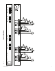
All terminals with common suffix (P) “1P, 2P ...” are the same polarity.
Input:
• Selectable115VAC60Hzor230VAC50/60Hzinput.
Output:
• Eight(8)orsixteen(16)individuallyselectable
24VAC or 28VAC power outputs with OFF position.
• Maximum1ampperoutput.
• Individualelectronicallyisolatedoutputs.
• Eight(8)orsixteen(16)powerLEDindicators.
• ExternalautomotivebladefusesorPTCprotectedoutputs.
• Surgesuppression.
Features:
• Illuminatedpowerdisconnectcircuitbreakerwith
manual reset.
• Removableterminalblockswithlockingscrewflange.
• Easeofinstallationsavestimeandeliminatescostlylabor.
Mechanical:
• Unitscanberack,wallorshelfmounted.
• Modular1UstandardEIA19”rackmountchassis
• EnclosureDimensions(HxWxDapprox.):
1.625” x 19.125” x 8.5” (41.3mm x 486mm x 216mm).