CCTV Rack Mount Power Supplies Installation Guide Models Include: Vertiline16 Vertiline16D - 24VAC or 28VAC @ 10 amp - Sixteen (16) fuse protected outputs - 24VAC or 28VAC @ 10 amp - Sixteen (16) PTC protected outputs Vertiline166 Vertiline166D - 24VAC or 28VAC @ 14 amp - Sixteen (16) fuse protected outputs - 24VAC or 28VAC @ 14 amp - Sixteen (16) PTC protected outputs Rev. 031808 More than just power.
Overview: Altronix Vertiline CCTV Rack Mount Power Supplies provide 16 power outputs in a space saving 1U EIA 19” rack mount chassis which may be rack, wall or shelf mounted. The units feature individually selectable 24VAC and/or 28VAC power outputs with surge suppression. Vertiline CCTV Rack Mount Power Supplies are also available in eight (8) and twentyfour (24) output models with various power ratings. Specifications: • Selectable 115VAC 60 Hz/230VAC 50/60 Hz input.
9. Connect the power outputs of terminals marked [1P & 1N] to the power inputs of camera 1 (Fig. 2, pg. 5). Repeat this step for each additional camera (Outputs 2-16). After wiring is completed insert terminal block into the corresponding connector and secure by tightening the screws. 10. Upon completion of wiring, set illuminated master power disconnect circuit breaker to the ON (RESET) position (Fig. 3, pg. 6). 11.
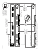
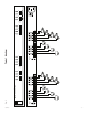
-4- Vertiline16 N 16 P N 15 P N 14 P N 13 P N 12 P N 11 P N 10 N 16 P N 15 P N 14 P N 13 P N 12 P N 11 P N 10 P N P N 1 9 9 3 4 28VAC OFF 24VAC P 1d - Main Fuse: Protects the transformer against overload. P 2 5 1a - LED(s) 1-16: Power LED indicators. 6 8 N 8 P N 7 P N 6 P N 5 Main Fuse 1-8 N 8 P N 7 P N 6 P N 5 1e - Power Outputs: 24VAC or 28VAC.
Vertiline16 -5- Main Fuse 9-16 OFF RESET Fig.
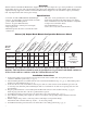
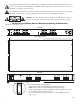
The lightning flash with arrow head symbol within an equilateral triangle is intended to alert the user to the presence of an insulated “DANGEROUS VOLTAGE” within the products enclosure that may be of sufficient magnitude to constitute an electric shock. The exclamation point within an equilateral triangle is intended to alert the user to the presence of important operating and maintenance (servicing) instructions in the literature accompanying the appliance.
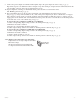
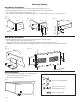
Mounting Options: Rack Mount Installation 1- Remove factory installed screws from both sides of rack chassis (Fig. 4a). 2- Install mounting brackets (A) on the left and right side of rack chassis using the two (2) flat head screws (B) (included) (Fig. 4b). 3- Place unit into desired EIA 19” rack position and secure with mounting screws (not included) (Fig. 4c). Fig. 4 Fig. 4b Fig. 4a Top Fig.
Notes: Altronix is not responsible for any typographical errors. Altronix Corp. 140 58th Street, Brooklyn, New York 11220 USA, 718-567-8181, fax: 718-567-9056 web site: www.altronix.com, e-mail: info@altronix.com, Lifetime Warranty, Made in U.S.A.