
Installation Instructions Owner manual

28VAC
OFF
24VAC
1
2
3 4 5
6
7 8 9 10 11 12 13 14 15 16
28VAC
OFF
24VAC
OFF
RESET
AC POWER
13141516
N
P
N
P
N
P
N
P
9101112
N
P
N
P
N
P
N
P
Main Fuse
9-16
5678
N
P
N
P
N
P
N
P
1234
N
P
N
P
N
P
N
P
Main Fuse
1-8
AC POWER
13141516
N
P
N
P
N
P
N
P
9101112
N
P
N
P
N
P
N
P
Main Fuse
9-16
5678
N
P
N
P
N
P
N
P
1234
N
P
N
P
N
P
N
P
Main Fuse
1-8
- 4 - Vertiline16C
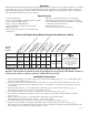
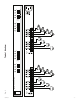
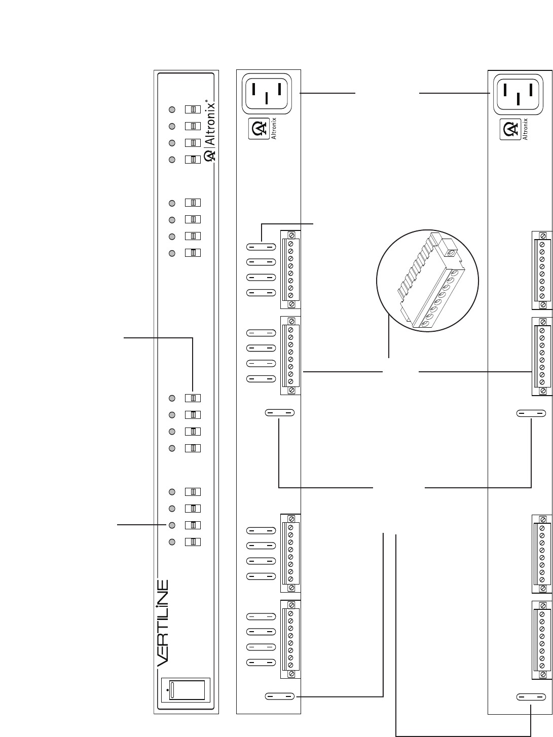
1b - Output voltage switches:
Selects 24VAC or 28VAC
or OFF for each output.
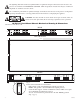
1c - Main Fuse:
Protects the
transformer
against overload.
1a - LED(s) 1-16:
Power LED indicators.
1f - IEC 320
Connector:
115VAC 60Hz
(grounded line
cord included).
Fig. 1
1d - Power
Outputs: 24VAC
or 28VAC.
1e - Output Fuses:
Automotive blade fuses.
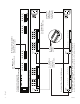
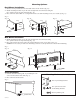
Vertiline16C, Vertiline16CD,
Vertiline166C or Vertiline166CD (front)
Vertiline16C or Vertiline166C (rear)
Vertiline16CD or Vertiline166CD (rear)
Vertiline16CD and Vertiline166CD do not have output fuses on the rear of the rack
mount chassis. The output PTCs are located on the inside of the rack mount chassis.