
Installation Guide

Tango8P(CB) - PoE Driven Multi-Output Power Supply Installation Guide - 5 -
Wiring:
Use 18 AWG or larger for all low voltage power connections.
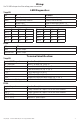
LED Diagnostics:
Tango1B
LED ON BLINKING
Input Input voltage is present. Input voltage not present.
Battery Normal operating condition. Battery is low or missing.
PoE Indicates Class. Refer to table below Classes 3-8
Supervision PoE Fail or BAT Fail. NC dry contact 30V 1A (not an LED)
Class Green Red Blue Class Green Red Blue
Class 1 – – – Class 5 On Off On
Class 2 – – – Class 6 On Off On
Class 3 Off Off Off Class 7 On On On
Class 4 Off On Off Class 8 On On On
PDS8:
LED ON
Green 12VDC Output.
Green and Red 24VDC Output.
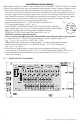
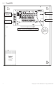
Terminal Identification:
Tango1B
Terminal/RJ45 Legend Function/Description
PoE+ Data Input IEEE802.3bt Input
(Fig. 2b, pg. 4).
Data Output Passes Data to Switch
(Fig. 2a, pg. 4)
C FAIL NC Power and Battery Fail (Fig. 2c, pg. 4).
+ 12V – 12VDC output
(Fig. 2d, pg. 4).
+ 24V – 24VDC output
(Fig. 2e, pg. 4).
+ BAT – Lithium Iron Phosphate battery backup
(Fig. 2f, pg. 4).
8-Pin Connector
(Fig. 2g, pg. 4) Facilitates electrical connection to PDS8(CB).
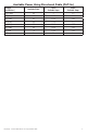
PDS8:
Terminal Legend Function/Description
+ INP1 – Factory connected to Tango1B. Do not use these terminals.
+ INP2 – Factory connected to Tango1B. Do not use these terminals.
P [OUT1-OUT8] Positive DC power outputs.
N [OUT1-OUT8] Negative DC power outputs.