
Installation Guide

Tango8AP(CB) - PoE Driven Multi-Output Power Supply/Charge With Access Power Controller - 5 -
Installation Instructions:
Wiring methods shall be in accordance with the National Electrical Code/NFPA 70/NFPA 72/ANSI, the Canadian
Electrical Code and with all local codes and authorities having jurisdiction. Product is intended for indoor use only.
1. Mount unit in desired location. Mark and predrill holes in the wall to line up with the top two keyholes in
the enclosure. Install two upper fasteners and screws in the wall with the screw heads protruding. Place the
enclosure’s upper keyholes over the two upper screws, level and secure. Mark the position of the lower two
holes. Remove the enclosure. Drill the lower holes and install the two fasteners. Place the enclosure’s upper
keyholes over the two upper screws. Install the two lower screws and make sure to tighten all screws
(Enclosure Dimensions, pg. 12). Secure enclosure to earth ground.
Tango1B:
2. Connect IEEE802.3bt PSE from PoE source to RJ45 Jack marked [PoE+ Data Input] on the Tango1B board
(Fig. 1b, pg. 5). If Data pass-through is required, connect another IEEE802.3bt PSE to RJ45 Jack marked
[Data Output] (Fig. 1a, pg. 5).
CAUTION: Do not touch exposed metal parts.
There are no user serviceable parts inside. Refer installation and servicing to qualified service personnel.
3. When the use of stand-by batteries is desired, they must be Lithium Iron Phosphate (LiFePO
4
).
Connect batteries to the terminals marked [+ BAT –] on Tango1B (battery leads included) (Fig. 1f, pg. 5).
4. Connect appropriate signaling notification devices to terminals marked [C FAIL NC] (Fig. 1c, pg. 5)
supervisory relay output.
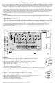
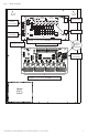
Fig. 1 - Tango1B with PDS8 stacked above
1a
1b
1c
1d
1e
1f
PDS8
PDS8CB
Dual Voltage
Power Distribution
Module
+ INP1
--
PWR1 +
OFF
IN1
IN2
Out1
<
1 off 2
>
PWR1 +
PWR2 +
PWR2 +
COM (--- )
COM (--- )
+ INP2
--
IN2 Fuse
IN1 Fuse
Common Power Outputs (NEG)
N
P
OUT1 OUT2 OUT3 OUT4 OUT5 OUT6 OUT7 OUT8
1 2 3 4 5 6 7 8
10
10
3
3
333333
Out2
<
1 off 2
>
Out3
<
1 off 2
>
Out4
<
1 off 2
>
Out5
<
1 off 2
>
Out6
<
1 off 2
>
Out7
<
1 off 2
>
Out8
<
1 off 2
>
1g
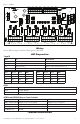
PDS8(CB):
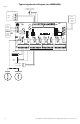
1. Ensure all output jumpers [OUT1 - OUT8] on PDS8(CB) are placed in the
OFF (center) position marked [•] (Fig. 2, pg. 5).
2. Set each output [OUT1 - OUT8] to route power from Input 1 or Input 2
(jumper position 1 or 2) (Fig. 1, 2, pg. 5, Fig. 3 pg. 6).
IN1 = 24VDC, IN2 = 12VDC.
Note: Measure output voltage before connecting devices.
This helps avoiding potential damage.
3. Connect devices to terminal pairs 1 to 8, marked [P (Positive) - OUT1-OUT8, N (Negative)]
(Fig. 1, pg. 5, Fig. 3 pg. 6).
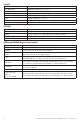
ACMS8(CB):
1. Ensure all output jumpers [PWR1] - [PWR8] are placed in the
OFF (center) position (Fig. 3, pg. 5).
2. Set each output [OUT1] - [OUT8] to route power from Input 1 or 2 (Fig. 3, pg. 5).
Note: Measure output voltage before connecting devices.
This helps avoiding potential damage.
3. Turn power off before connecting devices.
OFF
IN1
IN2
Fig. 2
PWR1
PWR2
OFF
Fig. 3