
Installation Guide


Tango8A(CB) - PoE Driven Access Controller - 5 -
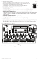
PWR1
+
PWR2
+
COM -
COM -
PWR2
+
PWR1
+
+ PWR2
--
+ PWR1
--
INP Logic
NO
<-->
NC
FACP
EN
<-->
DIS
FACP
FACP
FACP
Power 2
Power 1
+INP2--+INP1-- +INP3-- +INP4-- +INP5-- +INP6-- +INP7-- +INP8--
1
2
3
4
5
6
7
8
1
2
3
4
5
6
7
8
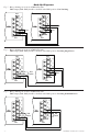
ONON
NC RST EOL +F +R
C GND GND -F -R
NO C NC COM NO C NC COM
Output 1 Output 2
NO C NC COM NO C NC COM
Output 3 Output 4
NO C NC COM NO C NC COM
Output 5 Output 6
NO C NC COM NO C NC COM
Output 7 Output 8
PoE+ Data
Input
Data
Output
Fig. 3
FACP
EN
<-- >
DIS
1
2
3
4
ON
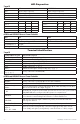
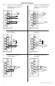
9. Fire Alarm Interface options:
A normally closed [NC], normally open [NO] input or polarity reversal input from
FACP signaling circuit will trigger selected outputs. To enable FACP Disconnect for
an output turn the corresponding DIP switch [SW1-SW8] ON.
To disable FACP disconnect for an output turn the corresponding DIP switch
[SW1-SW8] OFF. Switch is located directly to the left of the
Fire Alarm Interface Terminals.
Normally Open Input:
Wire your FACP relay and 10K resistor in parallel on terminals marked [GND] and [EOL].
Normally Closed Input:
Wire your FACP relay and 10K resistor in series on terminals marked [GND] and [EOL].
FACP Signaling Circuit Input Trigger:
Connect the positive (+) and negative (–) from the FACP signaling circuit output to the terminals marked
[+ FACP –]. Connect the FACP EOL to the terminals marked [+ RET –] (polarity is referenced in an
alarm condition).
Non-Latching Fire Alarm Disconnect:
Connect a jumper to the terminals marked [GND, RST].
Latching Fire Alarm Disconnect:
Connect a NO normally open reset switch to terminals marked [GND, RST].
10. FACP Dry NC output:
Connect desired device to be triggered by the unit’s dry contact output to the terminals marked [NC] and [C].
When [EOL JMP] is kept intact, the output is of 0 Ohm resistance in a normal condition.
When [EOL JMP] is clipped, a 10k resistance will be passed to next device when in a normal condition.
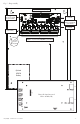
Fig. 4 - ACMS8 stacked above Tango1B.
Wiring:
Use 18 AWG or larger for all low voltage power connections.