
Installation Guide

- 2 - T3KAK33F16 Installation Guide
Overview:
Altronix T3KAK33F16 Trove Keyscan kit is pre-assembled and consist of Trove3KA3 enclosure/backplane with factory installed Altronix power
supply/chargers, transformer, and sub-assemblies. This kit also accommodates various combinations of Keyscan boards for up to sixteen (16)
doors in a single enclosure.
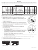
Configuration Chart:
Altronix
Model Number
120VAC
60Hz
Input
Current
(A)
Power
Supply
Boards
Input
Fuse
Rating
Power
Supply
Boards
Battery
Fuse
Rating
Nominal DC
Output Voltage
Maximum Supply
Current for Main and Aux.
Outputs on each
Power Supply board
and each ACM8 Access
Power Controller’s outputs
Fail-Safe/
Fail-Secure
or Dry Form
“C” Outputs
Current
Per
ACM8
Output
(A)
ACM8
Board
Input
Fuse
Rating
ACM8
Board
Output
Fuse
Rating
PD4UL
Board
Output
Fuse
Rating
[DC] [Aux]
24VDC
Output
Range
(V)
24VDC
Output
Range
(V)
T3KAK33F16
7.0
5A/
250V
10A/
32V
20.19-
26.4
20.19-
26.4
24VDC @ 5.8A 16 2.5
10A/
250V
3.5A/
250V
3.5A/
250V
Installation Instructions:
Wiring methods shall be in accordance with the National Electrical Code/NFPA 70/ANSI and with all local codes and authorities having jurisdiction.
Product is intended for indoor use only.
1. Remove backplane from enclosure. Do not discard hardware.
2. Mark and predrill holes in the wall to line up with the top three keyholes in the enclosure.
Install three upper fasteners and screws in the wall with the screw heads protruding. Place the
enclosure’s upper keyholes over the three upper screws, level and secure. Mark the position of the
lower three holes. Remove the enclosure. Drill the lower holes and install the three fasteners.
Place the enclosure’s upper keyholes over the three upper screws. Install the three lower screws
and make sure to tighten all screws.
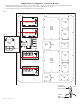
3. Mount included UL Listed tamper switch (Altronix Model TS112 or equivalent) in desired location,
opposite hinge. Slide the tamper switch bracket onto the edge of the enclosure approximately 2”
from the right side
(Fig. 1, pg. 2). Connect tamper switch wiring to the Access Control Panel input
or the appropriate UL Listed reporting device. To activate alarm signal open the door of the enclosure.
4. Mounting Included T16175 Transformer:
To prevent damage, T16175 is packed separately and needs to be installed by the user.
It is to be mounted on the left of the backplane, next to PD4UL power distribution board.
Please follow the steps below:
a. Orient T16175 so the terminals are facing down
(Fig. 4, 4a, pg. 3).
b. Put T16175’s upper mounting holes over two mounting pems on backplane and secure with
two (2) lock nuts
(Fig. 4, 4a, pg. 3).
c. Use included mounting bracket to secure T16175’s lower mounting holes. Align pems on the
bracket with T16175’s lower mounting holes and corresponding holes in the backplane.
Push the bracket’s pems through the holes and secure from the back side of the backplane
with two (2) lock nuts
(Fig. 2, pg. 2).
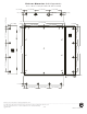
d. Connect AC power 115VAC, 50/60Hz to primary leads (black and white) from
terminal numbers 1 and 2 (Fig. 3, pg. 2).
e. Measure output voltage across the secondary leads (yellow and blue) from terminal numbers 7 and 12
(Fig. 3, pg. 2) before connecting
devices. This helps avoiding potential damage.
f. Connect PD4UL (factory mounted) to the secondary leads (yellow and blue) from terminal numbers 7 and 12 (Fig. 3, pg. 2).
5. Mount Keyscan boards to backplane, refer to
page 3.
6. Refer to the eFlow Power Supply/Charger Installation Guide for eFlow6NB, ACM8/CB Installation Guide for ACM8,
and
T16175 Installation Guide for T16175 for further installation instructions.
Fig. 1
Fig. 2
Fig. 3 - T16175 Wiring Configuration
Tamper Switch
(included)
To Access Control Panel or
UL Listed Reporting Device
Edge of
Enclosure
Enclosure
TKA3
Lock Nut
Mounting
Hole
Mounting Bracket
Terminals
T16175
16VAC (Secondary) Output115VAC (Primary) Input
43562
11
091112
87