
Installation Guide


Trove2 SS Kits - 3 -
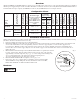
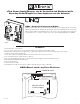
T2SSK7F8: Access Controller Position Chart for the S2-INST Installation Kit:
1. Align S2-INST mounting holes with pems on TSS2 (Fig. 2, pg. 3).
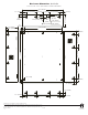
2. Attach S2-INST to backplane with lock nuts (provided) (Fig. 2a, pg. 3).
3. Mount backplane to enclosure with hardware.
4. Fasten TSS2 backplane to Trove2 enclosure utilizing hardware (provided).
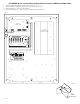
Fig. 2
Pem
Lock nut
S2-INST Bracket
Backplane
S2-INST
Installation Kit For
S2 Network Node
Altronix
eFlow104NB
– DC +– BAT +
L G N
OUTPUT 1 OUTPUT 2 OUTPUT 3 OUTPUT 4 OUTPUT 5 OUTPUT 6 OUTPUT 7 OUTPUT 8
NC C NO COM NC C NO COM NC C NO COM NC C NO COM NC C NO COM NC C NO COM NC C NO COM NC C NO COM
IN GND IN GND IN GND IN GNDIN GND IN GND IN GND IN GND
1 2 3 4
5 6 7 8
INPUT
TRIGGER
10A 250V
+INP- T + RET-
NO C NC
FACP INTERFACE
Power Control
- + - +
F1 F2 F3 F4 F5 F6 F7 F8
MAIN
TRG
FACP
1 2 3 4
1 2 3 4
ON
ON
1 2 3 4
1 2 3 4
ON
ON
Altronix
ACM8
+ INP1
--
DM1 +
OFF
IN1
IN2
Out1
<
1 off 2
>
DM1 +
DM2 +
DM2 +
Common (--- )
Common (--- )
+ INP2
--
IN2 Fuse
IN1 Fuse
Common Power Outputs (NEG)
N
P
OUT1 OUT2 OUT3 OUT4 OUT5 OUT6 OUT7 OUT8
1 2 3 4 5 6 7 8
10
10
3
3
3333 33
Out2
<
1 off 2
>
Out3
<
1 off 2
>
Out4
<
1 off 2
>
Out5
<
1 off 2
>
Out6
<
1 off 2
>
Out7
<
1 off 2
>
Out8
<
1 off 2
>
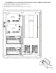
Altronix PDS8
Altronix VR6 mounted under PDS8
RSB1
Fig. 2a