
Installation Instructions


Trove SALTO ULXB Kits Installation Guide - 3 -
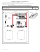
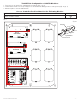
TRG
TRIGGER
INPUT
LED1 LED2 LED3 LED4
MAIN
OUTPUT 1
NC C NO COM NC C NO COM NC C NO COM NC C NO COM
OUTPUT 2 OUTPUT 3
IN GND
1
IN GND
2
IN GND
3
IN GND
4
OUTPUT 4
-- +
CONTROL
-- +
POWER
+INP- T +RET-
INTERFACE
NO C NC
FACP
Altronix - ACM4
OUT1 OUT2 OUT3 OUT4 OUT5 OUT6 OUT7 OUT8
Common Power Outputs (NEG)
P
N
+ INP1 - + INP2 -
PWR1+
PWR2+
COM (-)
PWR2+
COM (-)
P
N
Fuse1
Fuse2 Fuse3 Fuse4 Fuse5 Fuse6 Fuse7 Fuse8
IN1 Fuse
IN2 Fuse
PWR1+
Altronix - PDS8
1 2 3 4 5 6 7 8
Altronix VR6 is mounted under PDS8
A A
BAT FAIL NC C NO NC C NO
AC FAIL
AC DC BAT
+BAT-
+ DC -
L G N
OFF - 24V
ON - 12V
ON
Altronix
AL600ULXB
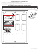
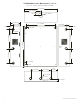
T1SAK34: Configuration of SALTO Modules:
1. Fasten spacers onto metal pems configuration (A) of backplane (Fig. 2, pg. 3).
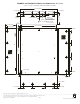
2. Position SALTO modules over corresponding spacers and mount them utilizing pan head screws (provided) (Fig. 2a, pg. 3).
3. Mount backplane to enclosure with hardware.
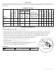
Access Controller Position Chart for the Following Models:
SALTO Access Controller Pem Mounting
CU42E0, CU4200 or CU4EB8
A
Fig. 2
Pem
Spacer
HS4 Module
Backplane
Pan Head Screw
Fig. 2a