
Installation Guide


- 4 - Trove Keri Systems Kits
T2KSK7F12: Installation Instructions for Keri Systems Access Controllers
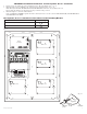
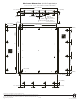
1. Fasten spacers (provided) into pem configuration (A) or (B) of backplane (Fig. 2, pg. 3).
2. Mount boards to spacers utilizing 5/16” pan head screws (provided) (Fig. 2a, pg. 3).
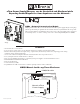
Note: Keri Systems NXT-2D-MSCNE and NXT-4D-MSCNE boards have one (1) RJ45 jack each.
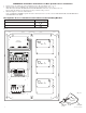
Please make sure that they are mounted correctly, as shown in Fig. 2 below.
3. Mount backplane to enclosure with hardware.
If use of NXTWI or NXTRM3 expansion boards is desired, there is no need to remove NXT-2D-MSCNE, NXT-4D-MSCNE or
NXT-4X4NE from the TKS2.
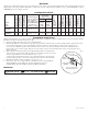
Keri Systems Access Controller Position Chart for the Following Models:
Keri Systems Board Pem Mounting
NXT-2D-MSCNE, NXT-4D-MSCNE A
NXT-4X4NE B
Pem
Spacer
Keri Systems
Board
Backplane
Pan Head
Screw
Fig. 2a
Altronix ACMS8
PWR1
+
PWR2
+
COM -
COM -
PWR2
+
PWR1
+
+ PWR2
--
+ PWR1
--
+ INP1
--
DM1 +
OFF
IN1
IN2
Out1
<
1 off 2
>
DM1 +
DM2 +
DM2 +
Common (--- )
Common (--- )
+ INP2
--
IN2 Fuse
IN1 Fuse
Common Power Outputs (NEG)
N
P
OUT1 OUT2 OUT3 OUT4 OUT5 OUT6 OUT7 OUT8
1 2 3 4 5 6 7 8
10
10
3
3
3333 33
Out2
<
1 off 2
>
Out3
<
1 off 2
>
Out4
<
1 off 2
>
Out5
<
1 off 2
>
Out6
<
1 off 2
>
Out7
<
1 off 2
>
Out8
<
1 off 2
>
Altronix PDS8
Altronix VR6 mounted under PDS8
Altronix
eFlow104NB
– DC +– BAT +
L G N
TRG
TRIGGER
INPUT
ACM4
ACCESS POWER
CONTROLLER
LED1 LED2 LED3 LED4
MAIN
OUTPUT 1
NC C NO COM NC C NO COM NC C NO COM NC C NO COM
OUTPUT 2 OUTPUT 3
IN GND
1
IN GND
2
IN GND
3
IN GND
4
OUTPUT 4
-- +
CONTROL
-- +
POWER
+INP- T +RET-
INTERFACE
NO C NC
FACP
Altronix
ACM4
RJ45 Jack
RJ45 Jack
RJ45 Jack
A
A
A
B
B
B
Fig. 2