
Installation Guide


T2HNK7F8 - 5 -
Altronix
eFlow104NB
– DC +– BAT +
L G N
OUTPUT 1 OUTPUT 2 OUTPUT 3 OUTPUT 4 OUTPUT 5 OUTPUT 6 OUTPUT 7 OUTPUT 8
NC C NO COM NC C NO COM NC C NO COM NC C NO COM NC C NO COM NC C NO COM NC C NO COM NC C NO COM
IN GND IN GND IN GND IN GNDIN GND IN GND IN GND IN GND
1 2 3 4
5 6 7 8
INPUT
TRIGGER
10A 250V
+INP- T + RET-
NO C NC
FACP INTERFACE
Power Control
- + - +
F1 F2 F3 F4 F5 F6 F7 F8
MAIN
TRG
FACP
1 2 3 4
1 2 3 4
ON
ON
1 2 3 4
1 2 3 4
ON
ON
Altronix
ACM8
+ INP1
--
DM1 +
OFF
IN1
IN2
Out1
<
1 off 2
>
DM1 +
DM2 +
DM2 +
Common (--- )
Common (--- )
+ INP2
--
IN2 Fuse
IN1 Fuse
Common Power Outputs (NEG)
N
P
OUT1 OUT2 OUT3 OUT4 OUT5 OUT6 OUT7 OUT8
1 2 3 4 5 6 7 8
10
10
3
3
3333 33
Out2
<
1 off 2
>
Out3
<
1 off 2
>
Out4
<
1 off 2
>
Out5
<
1 off 2
>
Out6
<
1 off 2
>
Out7
<
1 off 2
>
Out8
<
1 off 2
>
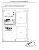
Altronix PDS8
Altronix VR6 mounted under PDS8
Honeywell
NX4IN or NX4OUT
Honeywell
NX4IN or NX4OUT
Honeywell
NX4IN or NX4OUT
Honeywell
NX4IN or NX4OUT
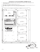
Fig. 4
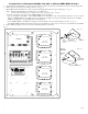
Configuration of Honeywell NX4IN or NX4OUT Boards:
1. Align Honeywell NX4IN or NX4OUT boards on the backplane to match the boards’ mounting holes with
corresponding pems.
2. Fasten spacers (provided) onto metal pems (Fig. 4a, pg. 5).
3. Mount Honeywell NX4IN or NX4OUT boards to spacers utilizing pan head screws (provided) (Fig. 4a, pg. 5).
4. Fasten THN2 backplane to Trove2 enclosure utilizing hardware (provided).
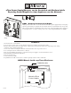
Pem
Spacer
Honeywell
Access Controller
Backplane
Pan Head
Screw
Fig. 4a