
Installation Guide


Trove CDVI Kits
- 3 -
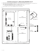
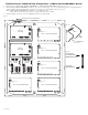
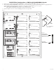
T1CVK3F4: Configuration of CDVI A22K/A22NB/ADH10 Boards
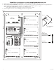
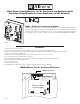
1. Fasten spacers (supplied with A22K/A22NB/ADH10) to CDVI A22K/A22NB/ADH10 board (Fig. 2b, pg. 3).
2. Mount CDVI A22K/A22NB/ADH10 boards into the correct positions (Fig. 2, pg. 3) by postioning spacers over appropriate holes
on the backplane and depressing down on board to secure spacer to the backplane (Fig. 2a, 2b, pg. 3).
Note: CDVI A22K/A22NB/ADH10 boards have one (1) RJ45 jack each.
Please make sure that they are mounted correctly, as shown in Fig. 2 below.
3. Fasten backplane to Trove2 enclosure utilizing pan head screws (provided).
Fig. 2
NC C NO NC
C NO
AC FAIL BAT FAIL
TRIGGER
AC DCAC1
EOL NO GND
SUPERVISED RESET
+AUX-
- BAT +- DC +
Altronix
eFlow6NB
L G N
OFF - 24V
ON - 12V
ON
--- +
Control
--- +
Power
NO C NC
FACP
INTERFACE
+ INP --- T + RET ---
TRG
TRIGGER
INPUT
IN GND
1
NC C NO COM
OUTPUT 1
NC C NO COM
OUTPUT 2
NC C NO COM
OUTPUT 3
NC C NO COM
OUTPUT 4
IN GND
3
IN GND
4
IN GND
2
LED1 LED2 LED3 LED4
SW1 SW2 SW3
SW4
MAIN
Altronix
ACM4
RJ45 Jack
RJ45 Jack
CDVI
A22K/A22NB/ADH10
CDVI
A22K/A22NB/ADH10
Spacer
CDVI - A22K/A22NB/ADH10
Access Controller
Backplane
Fig. 2a
Plastic Spacer
pre-mounted into
CDVI Atrium modules
Insert into
TC1 backplane
Fig. 2b