
Installation Guide

- 4 - Trove HID VertX Kits
T2VK7F8: Installation Instructions for HID VertX
®
Access Controllers
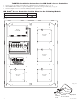
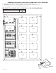
1. Fasten spacers (provided) onto metal pems configuration (A) of backplane (Fig. 3, pg. 4).
2. Mount HID VertX
®
modules to spacers utilizing 7/8” pan head screws (provided) (Fig. 3a, pg. 4).
3. Fasten backplane to Trove2 enclosure utilizing hardware (provided).
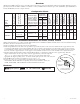
HID VertX
®
Access Controller Position Chart for the Following Models:
Sub-Assembly Pem Mounting
V100, V200, V300, V1000, V2000 A
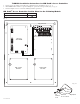
Altronix
eFlow104NB
– DC +– BAT +
L G N
OUTPUT 1 OUTPUT 2 OUTPUT 3 OUTPUT 4 OUTPUT 5 OUTPUT 6 OUTPUT 7 OUTPUT 8
NC C NO COM NC C NO COM NC C NO COM NC C NO COM NC C NO COM NC C NO COM NC C NO COM NC C NO COM
IN GND IN GND IN GND IN GNDIN GND IN GND IN GND IN GND
1 2 3 4
5 6 7 8
INPUT
TRIGGER
10A 250V
+INP- T + RET-
NO C NC
FACP INTERFACE
Power Control
- + - +
F1 F2 F3 F4 F5 F6 F7 F8
MAIN
TRG
FACP
1 2 3 4
1 2 3 4
ON
ON
1 2 3 4
1 2 3 4
ON
ON
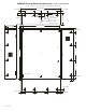
Altronix
ACM8
+ INP1
--
DM1 +
OFF
IN1
IN2
Out1
<
1 off 2
>
DM1 +
DM2 +
DM2 +
Common (--- )
Common (--- )
+ INP2
--
IN2 Fuse
IN1 Fuse
Common Power Outputs (NEG)
N
P
OUT1 OUT2 OUT3 OUT4 OUT5 OUT6 OUT7 OUT8
1 2 3 4 5 6 7 8
10
10
3
3
3333 33
Out2
<
1 off 2
>
Out3
<
1 off 2
>
Out4
<
1 off 2
>
Out5
<
1 off 2
>
Out6
<
1 off 2
>
Out7
<
1 off 2
>
Out8
<
1 off 2
>
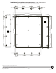
Altronix PDS8
Altronix VR6 is mounted under PDS8
HID VertX
®
Module
A
HID VertX
®
Module
A
HID VertX
®
Module
A
HID VertX
®
Module
A
Fig. 3
Pem
Spacer
HID VertX
®
Access Controller
Backplane
Pan Head
Screw
Fig. 3a