
Installation Guide


T1RV3F4 - 5 -
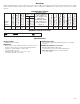
PDS8/VR6
OUT1
OUT2 OUT3 OUT4 OUT5 OUT6 OUT7 OUT8
1 2 3 4 5 6 7 8
Common Power Outputs (NEG)
P
N
+ INP1 - + INP2 -
PWR1+
PWR2+
COM(-)
PWR1+
COM(-)
P
N
PWR1+
ACM4
--- +
Control
--- +
Power
NO C NC
FACP
INTERFACE
+ INP --- T + RET ---
TRG
TRIGGER
INPUT
IN GND
1
NC C NO COM
OUTPUT 1
NC C NO COM
OUTPUT 2
NC C NO COM
OUTPUT 3
NC C NO COM
OUTPUT 4
IN GND
3
IN GND
4
IN GND
2
ACM4
ACCESS POWER
CONTROLLER
RoHS
MAIN
eFlow6NB
AC
L G N
DCAC1
1 min
enable
2 hr.
disable
OFF - 24V
ON - 12V
ON
TRIGGER EOL
SUPERVISED
--- BAT + --- DC +
NC C NO
AC FAIL
NC C NO
BAT FAIL
+ AUX ---
NO GND
RESET
To IEC
connector
VR6 is mounted under PDS8(CB)
A
A
A
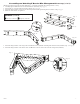
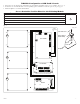
T1RV3F4: Configuration of HID VertX
®
Boards:
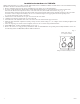
1. Fasten spacers onto metal pems configuration (A) of backplane depending on the access controller (Fig. 4, pg. 5).
2. Position access controller module over corresponding spacers and fasten screws into spacers (Fig. 4a, pg. 5).
3. Mount backplane to enclosure with hardware.
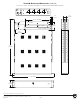
Access Controller Position Chart for the Following Models:
HID VertX
®
Sub-Assembly Pem Mounting
V100
A
V200
V300
V1000
V2000
Fig. 4
Pem
Spacer
Backplane
Power Supply or
Sub-Assembly
Pan Head Screw
Fig. 4a