
Installation Guide


- 4 - T1RV3F4
Installation Instructions for T1RV3F4:
Wiring methods shall be in accordance with the National Electrical Code/NFPA 70/ANSI, and with all local codes and authorities having
jurisdiction. Product is intended for indoor use only.
1. Remove backplane from enclosure prior to installing into rack cabinet (do not discard hardware).
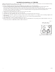
2. In order to mount included UL Listed tamper switch (Altronix Model TS112 or equivalent) turn the enclosure upside down.
Punch out the knockout in designated location, on the back of the unit, from outside of the drawer (Fig. 3, pg. 3).
Insert the tamper switch into the knockout from outside of the drawer with the button facing outwards and spaded connectors inside
the drawer. Connect tamper switch wiring to the Access Control Panel input or the appropriate UL Listed reporting device.
To activate alarm signal open the rack drawer.
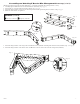
3. Slide the Trove rack enclosure into an open 2U location in the rack cabinet.
4. Utilizing proper fasteners attach front ears to the rack rails.
5. Attach the rear of the adjustable slides to the rear rails of the rack cabinet with the proper fasteners.
6. Make sure that all internal cofigurations (wiring, voltage selection, switch settings, etc.) are complete before mounting backplane back
into enclosure.
7. After all components are mounted on the backplane, attach it to the enclosure using included hardware.
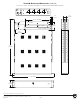
8. Mount HID VertX
®
boards to TV1R backplane, refer to page 5.
9. Refer to the eFlow Power Supply/Charger Installation Guide for eFlow6NB and corresponding sub-assembly Installation Guides for
the following models: ACM4, PDS8, VR6 for further instructions.
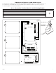
Fig. 3
Tamper Switch mounting location
Back of the drawer,
viewed from outside.