
Installation Guide


T1RAG3F8 - 5 -
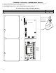
eFlow6NB
AC
L G N
DCAC1
1 min
enable
2 hr.
disable
OFF - 24V
ON - 12V
ON
TRIGGER EOL
SUPERVISED
--- BAT + --- DC +
NC C NO
AC FAIL
NC C NO
BAT FAIL
+ AUX ---
NO GND
RESET
To IEC
connector
ACMS8
PWR1
+
PWR2
+
COM -
COM -
PWR2
+
PWR1
+
+ PWR2
--
+ PWR1
--
VR6 is
mounted
under
ACMS8
A
A
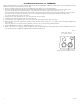
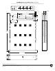
T1RAG3F8: Configuration of AMAG M4000 Modules:
1. Align the AMAG M4000 modules on the backplane to match the boards’ mounting holes with corresponding pems.
2. Fasten spacers (provided) onto metal pems (Fig. 4a, pg. 3).
3. Mount AMAG M4000 modules to spacers utilizing pan head screws (provided) (Fig. 4a, pg. 3).
4. Fasten TAG1R backplane to Trove1R rack enclosure utilizing hardware (provided).
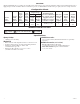
Position Chart for the Following Models:
M4000 Pem Mounting
M4000-DEC4, M4000-IOC20/16
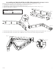
A
Fig. 4
Pem
Spacer
Backplane
Power Supply or
Sub-Assembly
Pan Head Screw
Fig. 4a