
Installation Instructions

Trove Openpath Kits - 3 -
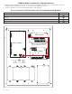
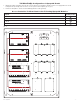
T1PHK1F4S(D): Configuration of Openpath Boards
1. Mount appropriate Openpath boards into the correct positions by postioning pre-mounted spacers over appropriate holes on the
backplane and depressing down on board to secure spacer to the backplane (Fig. 2, pg. 3).
2. Fasten TC1 backplane to Trove1 enclosure utilizing pan head screws (provided).
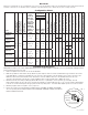
Access Controller Position Chart for the Following Openpath Modules:
Openpath Mounting Position
OP-ACC A
OP-EX-4E B
OP-EX-8E C
OP-16EM D
Fig. 2
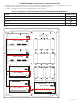
NC C NO NC
C NO
AC FAIL BAT FAIL
TRIGGER
AC DCAC1
EOL NO GND
SUPERVISED RESET
+AUX-
- BAT +- DC +
Altronix - eFlow4NB
L G N
OFF - 24V
ON - 12V
ON
--- +
Control
--- +
Power
NO C NC
FACP
INTERFACE
+ INP --- T + RET ---
TRG
TRIGGER
INPUT
IN GND
1
NC C NO COM
OUTPUT 1
NC C NO COM
OUTPUT 2
NC C NO COM
OUTPUT 3
NC C NO COM
OUTPUT 4
IN GND
3
IN GND
4
IN GND
2
LED1 LED2 LED3 LED4
MAIN
Altronix - ACM4(CB)
Altronix - PDS8(CB)
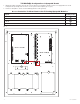
D
C
B
A
OUT1 OUT2 OUT3 OUT4 OUT5 OUT6 OUT7 OUT8
Common Power Outputs (NEG)
P
N
+ INP1 - + INP2 -
PWR1+
PWR2+
COM(-)
PWR2+
COM(-)
P
N
IN1 Fuse
IN2 Fuse
PWR1+
1 2 3 4 5 6 7 8
VR6 is mounted below PDS8(CB)
and connected via 8-pin connector