
Installation Guide


- 4 - Trove DMP Kits
T2DMK7F8: Configuration of DMP 734/734N Wiegand Modules:
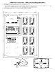
1. Fasten spacers (provided) to pems that match the hole pattern for DMP 734/734N Wiegand Modules (Fig. 3, pg. 4).
2. Mount DMP 734/734N modules into the correct positions (Fig. 3, pg. 4):
a. Remove DMP 734/734N board from the plastic housing. Use the base part of the housing to mount onto TDM2 (Fig. 3a, 3b, pg. 4).
b. Secure the base of DMP 734/734N to the spacers using provided 5/16” pan head screws.
c. Make all necessary connections before reassembling DMP 734/734N Wiegland modules.
3. Fasten TDM2 backplane to Trove2 enclosure utilizing hardware (provided).
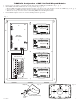
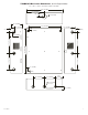
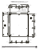
Fig. 3
Altronix
eFlow104NB
– DC +– BAT +
L G N
OUTPUT 1 OUTPUT 2 OUTPUT 3 OUTPUT 4 OUTPUT 5 OUTPUT 6 OUTPUT 7 OUTPUT 8
NC C NO COM NC C NO COM NC C NO COM NC C NO COM NC C NO COM NC C NO COM NC C NO COM NC C NO COM
IN GND IN GND IN GND IN GNDIN GND IN GND IN GND IN GND
1 2 3 4
5 6 7 8
INPUT
TRIGGER
10A 250V
+INP- T + RET-
NO C NC
FACP INTERFACE
Power Control
- + - +
F1 F2 F3 F4 F5 F6 F7 F8
MAIN
TRG
FACP
1 2 3 4
1 2 3 4
ON
ON
1 2 3 4
1 2 3 4
ON
ON
Altronix
ACM8
+ INP1
--
DM1 +
OFF
IN1
IN2
Out1
<
1 off 2
>
DM1 +
DM2 +
DM2 +
Common (--- )
Common (--- )
+ INP2
--
IN2 Fuse
IN1 Fuse
Common Power Outputs (NEG)
N
P
OUT1 OUT2 OUT3 OUT4 OUT5 OUT6 OUT7 OUT8
1 2 3 4 5 6 7 8
10
10
3
3
3333 33
Out2
<
1 off 2
>
Out3
<
1 off 2
>
Out4
<
1 off 2
>
Out5
<
1 off 2
>
Out6
<
1 off 2
>
Out7
<
1 off 2
>
Out8
<
1 off 2
>
Altronix PDS8
Altronix VR6 mounted under PDS8
DMP 734 or 734N
Wiegand
DMP 734 or 734N
Wiegand
DMP 734 or 734N
Wiegand
DMP 734 or 734N
Wiegand
DMP 734 or 734N
Wiegand
DMP 734 or 734N
Wiegand
DMP 734 or 734N
Wiegand
DMP 734 or 734N
Wiegand
Spacer
DMP 734 plastic housing
Backplane
Pan Head
Screw
Pem
Mounting
Spacer
Placement
Fig. 3bFig. 3a