
Installation Guide


StrikeIt4 - 5 -
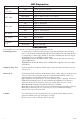
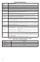
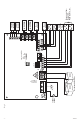
Terminal Identification:
Terminal
Legend
Function/Description
– 24V + 24VDC Auxiliary Output @ 0.8A. 19.8-26.4VDC for applications with battery back-up.
– 12V + 12VDC Auxiliary Output @ 0.5A.
– BAT + 24VDC Stand-by Battery Connection (Two (2) 12VDC batteries wired in series).
+ OUT 1 – Connect 24VDC Low Current Lock Device # 1. Note: Load connected not to exceed 1A.
+ OUT 2 – Connect 24VDC Low Current Lock Device # 2. Note: Load connected not to exceed 1A.
FACP / GND
Normally Closed Dry Contact from Fire Alarm Control
(100 Ohm maximum wiring resistance).
INP1 / GND
Normally Open Trigger input controls Output 1.
May be held closed for extended unlocking (100 Ohm maximum wiring resistance).
INP2 / GND
Normally Open Trigger input controls Output 2.
May be held closed for extended unlocking (100 Ohm maximum wiring resistance).
ADA IN1
Normally open trigger input for automatic door operator interface mode. Works similar to
INP1, but also causes ACT-1 relay to trigger momentarily (0.5 or 1 second, depending on
the position of DIP Switch # 3).
ADA IN2
Normally open trigger input for automatic door operator interface mode. Works similar to
INP2, but also causes ACT-2 relay to trigger momentarily (0.5 or 1 second, depending on
the position of DIP Switch # 3).
Trouble C, NC Indicates AC or battery trouble condition. Normally closed.
Follower 1
Follower 2
Normally open dry contacts following the operation of Output 1 and Output 2.
For Fail Safe devices: Relay closes when input is triggered and lock output power
is disconnected.
For Fail Secure devices: Relay closes when input is triggered and lock output power
is applied.
Note: Intended application for controlling ADA actuators/accessories.
ACT-1
ACT-2
Momentary normally open dry contacts following inputs [ADA IN1] and [ADA IN2],
ACT relays will activate following engagement of [ADA IN1] and [ADA IN2] inputs.
Adjust delay time for 0.5 seconds or 1 second to allow for lock hardware to fully activate
by using DIP Switch #3.
Note: Intended application for automatic operator activation.
Output1 and Output 2 Wiring Distance Table
(based on 1A max. load locking hardware):
Wire Gauge Distance
18 AWG Stranded 180 ft.
16 AWG Stranded 280 ft.
14 AWG Stranded 450 ft.
12 AWG Stranded 720 ft.