
Installation Guide


StrikeIt2 - 3 -
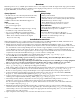
Overview:
StrikeIt2 operates one (1) 24VDC panic hardware device. It is designed to handle the high current surge panic hardware
locking devices demand. In addition, an auxiliary power output provides power for accessory devices such as card readers,
keypads, REX PIRs, electronic timers, relays, etc.
Specifications:
Installation Instructions:
Wiring methods shall be in accordance with the National Electrical Code/NFPA 70/NFPA 72/ANSI, and with all local
codes and authorities having jurisdiction. Product is intended for indoor use only.
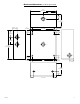
1. Mount unit in the desired location within protected premises (Maximum Wiring Distance Table, pg. 5). Mark and
predrill holes in the wall to line up with the top two keyholes in the enclosure. Install two upper fasteners and screws in
the wall with the screw heads protruding. Place the enclosure’s upper keyholes over the two upper screws; level and
secure. Mark the position of the lower two holes. Remove the enclosure. Drill the lower holes and install the two
fasteners. Place the enclosure’s upper keyholes over the two upper screws. Install the two lower screws and make sure
to tighten all screws (Enclosure Dimensions, pg. 7). Secure cabinet to earth ground.
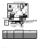
2. Connect AC power (115VAC 60Hz) to the terminals marked [L, G, N] (Fig. 1, pg. 5 & Fig. 2, pg. 6).
The AC LED (Green) will illuminate, indicating power is present.
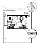
Keep power-limited wiring separate from non power-limited wiring (115VAC 60Hz Input, Battery Wires).
Minimum 0.25” spacing must be provided (Fig. 2, pg. 6).
CAUTION: Do not touch exposed metal parts. Shut branch circuit power before installing or servicing equipment.
There are no user serviceable parts inside. Refer installation and servicing to qualified service personnel.
3. Measure output voltage at the terminals marked [-- AUX +] and [-- OUT +] before connecting devices
(Fig. 1, pg. 5 & Fig. 2b, pg. 6). This helps avoiding potential damage.
Note: Voltage will be present on the output when the unit is not triggered and electric panic hardware is not connected.
4. Connect 24VDC panic hardware device to the terminals marked [-- OUT +] (Fig. 1, pg. 5 & Figs. 2 & 2b, pg. 6).
Be sure to observe polarity. Voltage should dissipate across output terminals when load is properly connected.
5. Connect Normally Open [NO] Dry Contacts from actuating devices such as an Access Control Panel, REX PIR,
Keypad, etc. to the terminals marked [GND, NO] (Fig. 1, pg. 5 & Fig. 2b, pg. 6).
6. Connect auxiliary devices to be powered (Keypads, REX motion detectors, electronic timers, external relays) to the
auxiliary power output terminals marked [-- AUX +] (Fig. 1, pg. 5 & Fig. 2b, pg. 6).
7. When using stand-by batteries, they must be lead acid or gel type. 4AH batteries will provide a 1/2 hour of
backup time. Connect two (2) 12VDC batteries wired in series to the terminals marked [-- BAT +].
For Access Control applications batteries are optional. When batteries are not used, a loss of AC will result in the
loss of output voltage (Fig. 2b, pg. 5).
8. Mount UL Listed tamper switch (Sentrol model 3012 or equivalent) at the top of the enclosure. Slide the tamper
switch bracket onto the edge of the enclosure approximately 2” from the right side (Fig. 2a, pg. 6). Connect tamper
switch wiring to the Access Control Panel input or the appropriate UL Listed reporting device. To activate alarm
signal open the door of the enclosure.
9. Upon completion of the wiring secure enclosure door with screws or cam lock.
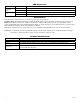
Agency Approval:
• ULListedforAccessControlSystemUnits(UL294).
• CULListed-CSAStandardC22.2No.205-M1983,
Signal Equipment.
•CSFM-CaliforniaStateFireMarshalApproved.
Input:
• 115VAC60Hz,7amp.
• One(1)N/Otriggerinput.
Output:
• One(1)23.2-24VDClockoutputratedupto16amp
for 300ms, 0.5 amp continuous hold current.*
• One(1)23.2-24VDCfilteredregulatedauxiliary
output rated @ 0.5 amp continuous supply current*
* Note: Total combined current for the outputs
may not exceed 1 amp.
Battery Backup:
• Batteryleadsincluded.
• Built-inchargerforsealedleadacidorgeltypebatteries.
• Automaticswitchovertostand-bybatterywhenACfails.
• Maximumchargecurrent0.3amp.
• When4AHbatteriesareused,batterycapacity
for emergency stand-by is at least a 1/2 hour.
Visual Indicators:
• GreenACPowerLEDindicates115VACpresent.
• RedLEDindicatespresenceof24VDC.
Mechanical:
• EnclosureDimensions(HxWxDapprox.):
8.5” x 7.5” x 3.5” (215.9mm x 190.5mm x 88.9mm)
• Enclosureaccommodatesuptotwo(2)
12VDC/4AH batteries.