
Installation Guide


StrikeIt1V Installation Guide - 9 -
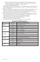
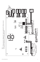
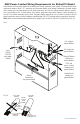
Fig. 3
Ground
Lug
Wire
Strap
(from
Enclosure
to Door)
Tamper Switch
220VAC Input
50/60Hz, 4A
FACP
GND
GND
– OUT1 +
+ BAT –
– OUT2 +
IN1
GND
IN2
LGN
25A 32V
25A
6.3A
6.3A 250V
AC
OUT1
TIMER
Manual Test
OUT2
TIMER
ON
Option 1-Option 2
24-5V Hold Voltage
Follow-up Delay 0.5-1 sec.
Fire Alarm Interface
1
2
3
4
Class 2 Dry
Location
Outputs
Battery
Outputs
FACP and
Access Control
Trigger Inputs
Aux. Outputs
Class 2 Dry
Class 2 Dry
Outputs
MIN
MAX
C NO C NO C NC +12VDC– +24VDC–
Delayed 1 Follower 1
C NO C NO
C NO C NO
Delayed 2 Follower 2
C NO C NO
FAULT
C NC
Optional Rechargeable
Stand-by Battery
Optional Rechargeable
Stand-by Battery
Fig. 3a
Fig. 3b
Note: StrikeIt1 is intended for use with VON DUPRIN
®
panic hardware devices.
VON DUPRIN
®
is a registered trademark of Allegion.