
Installation Guide


- 8 - StrikeIt1V Installation Guide
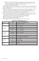
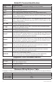
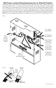
Note: For independent operation of Output 1 and 2, connect NO
dry contact between IN1 and GND and/or IN2 and GND.
For sequential operation of OUT1 and OUT2 install a jumper
between IN1 and IN2 and a jumper between both GND terminals.
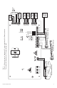
Battery + 24VDC
–
OUT1 and OUT2
Relock delay adjustment. Used to hold OUT1 or OUT2 energized
after a momentary closure across IN1 or IN2. Set for 0 seconds
for output to follow input. Turn clockwise to increase time.
FACP
GND
GND
– OUT1 +
+ BAT –
– OUT2 +
IN1
GND
IN2
LG N
25A 32V
25A
6.3A
6.3A 250V
AC
OUT1
TIMER
Manual Test
OUT2
TIMER
ON
Option 1 - Option 2
24-5V Hold Voltage
Follow-up Delay
0.5-1 sec.
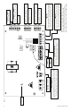
Fire Alarm Interface
1
2
3
4
Output 2
Output 1
AC Power LED
MIN
MAX
INP1
INP2
FAI
BAT
AC
Follower 2 - This relay will activate
immediately when OUTPUT 2 is energized.
C NO C NO C NC +12VDC– +24VDC–
Delayed 1 Follower 1
C NO C NO
C NO C NO
Delayed 2 Follower 2
C NO C NO
FAULT
C NC
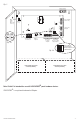
Fire Alarm Interface
Connect these terminals to a normally closed dry contact
that opens upon fire alarm activation.
Input #1
Connect normally open dry contacts from key switch,
timer, remote release or any maintained/momentary
switch. Output #1 energizes while input is closed.
Input #2
Connect normally open dry contacts from key switch,
timer, remote release or any maintained/momentary
switch. Output #2 energizes while input is closed.
12V Aux + Output –
12VDC @ 0.75A in alarm, 0.5A in stand-by
AC Supervision
24V Aux + Output –
20VDC-26.4VDC @ 0.75A
Delayed 2 - This relay will
activate after 0.5 sec. or 1 sec.
Follower 1 - This relay will activate
immediately when OUTPUT 1 is energized.
Delayed 1 - This relay will
activate after 0.5 sec. or 1 sec.
Fig. 2