
Installation Guide


StrikeIt1V Installation Guide - 5 -
b) With DIP switch [SW4] in the OFF position, the application of a FACP trigger input (open circuit)
while Input 1 and Input 2 are not triggered will cause the locked (de-energized) panic hardware
devices to unlock (energize). Follower relays will activate (energize).
Delayed relays will energize momentarily.
Note: With SW4 in the OFF position, the application of a FACP trigger input (open circuit) while Input 1 and
Input 2 are triggered will have no affect on the operation of Output 1 or Output 2 and their corresponding
Follower or Delayed relays.
10. When using stand-by batteries, they must be lead acid or gel type. 7AH batteries will provide 30 minutes of
backup time. Connect two (2) 12VDC batteries wired in series to the terminals marked [+ BAT –].
For Access Control applications batteries are optional, for Canadian applications batteries are required.
When batteries are not used, loss of AC will result in the loss of output voltage.
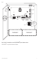
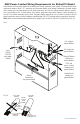
11. Mount UL Listed tamper switch (Sentrol model 3012 or equivalent) at the top of the enclosure. Slide the
tamper switch bracket onto the edge of the enclosure approximately 2” from the right side (Fig. 3, pg. 9).
Connect tamper switch wiring to the Access Control Panel input or the appropriate
UL Listed reporting device. To activate alarm signal open the door of the enclosure.
Note: Do not exceed voltage and current ratings of tamper switch.
Please refer to tamper switch installation instructions.
12. Upon completion of wiring secure enclosure door with screws or cam lock (supplied).
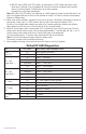
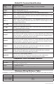
StrikeIt1V LED Diagnostics:
LED LED Status Panic Device Power Controller Status
Power -
Green (AC)
On Normal operating condition.
Off Loss of AC.
INP1 - Red
Trigger Input 1
On Output 1 - Energized.
Slow Blink Output 1 - Open Circuit.
Rapid Blink Output 1 - Short Circuit.
Off Output 1 - De-energized.
INP2 - Red
Trigger Input 2
On Output 2 - Energized.
Slow Blink Output 2 - Open Circuit.
Rapid Blink Output 2 - Short Circuit.
Off Output 2 - De-energized.
FAI - Green
On FACP Input triggered (alarm condition).
Off FACP normal (non-alarm condition).
BAT Trouble
Red
Off Normal condition.
On Manual test initiated.
Slow Blink Battery low or missing, active during manual test or AC failure.
AC Trouble
Green
Off AC normal.
Slow blink AC low or missing.