
Installation Guide

StrikeIt1V Installation Guide - 3 -
Overview:
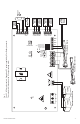
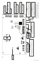
Altronix StrikeIt1V will operate up to two (2) 24VDC panic hardware devices simultaneously. It is designed to handle
the high current surge panic hardware locking devices demand. Each lock output has an adjustable relock delay
timer. It will control a pair of doors simultaneously or independently control two individual doors. It has a follower
relay for each output to trigger external relays, ADA push plate switches, etc. Delayed follower relays control
automatic door operators for doors that are always locked or for doors that are unlocked during the business day.
In addition, two un-switched auxiliary voltage outputs are provided for powering card readers, keypads, REX PIRs,
electronic timers, relays, etc. A configurable FACP interface will either provide power or remove power to the lock
outputs when activated. LED status indicators are provided to monitor AC power, FACP status and for lock output
wiring supervision. Intelligent logic provides protection against accidental shorting of lock outputs.
Specifications:
Input:
• Input 220VAC, 50/60Hz, 4A.
• Two (2) NO trigger inputs.
• Input fuse rating: 6.3A.
Outputs:
• Power options:
- Two (2) 20VDC to 26.4VDC individually
controlled lock outputs for applications with
battery back-up.
24VDC for applications without battery back-up
(US applications only).
Current rating 15A for 300ms, 0.75A continuous
supply current.
- 5V holding voltage with 20VDC to 26.4VDC
initial 100ms pulse.
Maximum total 5V holding current of both
outputs is 0.74A.
• One (1) 20VDC to 26.4VDC for applications with
battery back-up, 24VDC for applications in US not
requiring battery back-up.
Auxiliary output rated @ 0.75A continuous supply
current (Not affected by FACP trigger).
• One (1) 12VDC filtered regulated auxiliary output
rated @ 0.75A in alarm, 0.5A stand-by current
(Not affected by FACP trigger).
• Two (2) follower form “A” SPST relay outputs
rated @ 0.6A/28VDC.
Relays energize while input is closed.
• Two (2) delayed follower Normally Open relay
outputs rated @ 0.6A/28VDC.
Delay time is selectable 0.5 seconds or 1 second.
Energized duration is 1 second.
• Trouble relay output indicating low DC
output voltage.
Battery Backup:
• Battery leads included.
• Battery fuse rating: 25A/32V.
• Maximum charge current 650mA.
• Built-in charger for sealed lead acid or
gel type batteries.
• Automatic switch over to stand-by battery
when AC fails.
• When 7AH batteries are used, battery capacity
for emergency stand-by is 30 minutes.
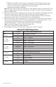
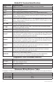
Visual Indicators:
• Green AC Power LED indicates 220VAC present.
• Red trigger input LEDs indicate panic device
status/trouble (activated, short or open circuit).
• Green Fire Alarm Interface (FAI) LED indicates
FACP disconnect is activated.
• Red Battery LED indicates low battery during
AC failure and manual test.
• Green AC LED indicates loss of AC trouble
(not active during manual test sequence).
Fire Alarm Disconnect:
• Normally Closed FACP trigger input.
• Programmable Fire Alarm Disconnect options:
- Removes power to outputs and disables delayed
follower relays.
- Connects power to lock outputs and enables
delayed follower relays.
Additional Features:
• Manual testing to allow to tests battery conditions.
• Adjustable panic release from 1 sec. to 30 secs.
Note: Follower and Delay relay turns off when the
potentiometer selected time elapses after release of
the input trigger.
• Cam lock included.
Enclosure Dimensions (H x W x D approx.):
13.5” x 13” x 3.25”
(342.9mm x 330.2mm x 82.6mm)