® StrikeIt1V Panic Device Power Controller Installation Guide Rev. 052915 More than just power.TM Installing Company: ________________ Service Rep.
Table of Contents: Overview. . . . . . . . . . . . . . . . . . . . . . . . . . . . . . . . . . . . . . . . . . . . . . . . . . . . . . . . . . . . . . . . . . pg. 3 Specifications. . . . . . . . . . . . . . . . . . . . . . . . . . . . . . . . . . . . . . . . . . . . . . . . . . . . . . . . . . . . . . pg. 3 StrikeIt1V Installation Instructions . . . . . . . . . . . . . . . . . . . . . . . . . . . . . . . . . . . . . . . . . . . . . . pg. 4 StrikeIt1V LED Diagnostics. . . . . . . . . . . . . . . . . . . . .
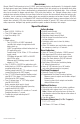
Overview: Altronix StrikeIt1V will operate up to two (2) 24VDC panic hardware devices simultaneously. It is designed to handle the high current surge panic hardware locking devices demand. Each lock output has an adjustable relock delay timer. It will control a pair of doors simultaneously or independently control two individual doors. It has a follower relay for each output to trigger external relays, ADA push plate switches, etc.
Strikelt1V Installation Instructions: Wiring methods shall be in accordance with the National Electrical Code/NFPA 70/NFPA 72/ANSI, and with all local codes and authorities having jurisdiction. Product is intended for indoor use only. For Canadian installations shielded wiring of appropriate gauge must be used. Unit is to be serviced by authorized personnel and de-energized prior to opening. 1. Mount unit in desired location within protected premises (Maximum Wiring Distance, pg. 6).
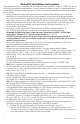
b) With DIP switch [SW4] in the OFF position, the application of a FACP trigger input (open circuit) while Input 1 and Input 2 are not triggered will cause the locked (de-energized) panic hardware devices to unlock (energize). Follower relays will activate (energize). Delayed relays will energize momentarily.
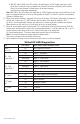
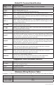
StrikeIt1V Terminal Identification: Terminal Legend L, G, N + 12VDC – + 24VDC – + BAT – – OUT 1 + – OUT 2 + FACP / GND IN1 / GND IN2 / GND Delayed 1 Delayed 2 Follower 1 Follower 2 Supervision Function/Description Connect 220VAC, 50/60 Hz to these terminals: L to Hot, N to Neutral. 12VDC Auxiliary Output @ 0.75A in alarm, 0.5A in stand-by. 24VDC Auxiliary Output @ 0.75A. 20VDC to 26.4VDC for applications with battery back-up. 24VDC Stand-by Battery Connection (Two (2) 12VDC batteries wired in series).
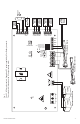
--- 6.3A 12VDC G --- N + 12VDC Rechargeable Batteries + L 6.3A 250V + BAT – 25A 25A 32V ON Panic Hardware Device – OUT2 + Panic Hardware Device – OUT1 + INP1 INP2 FAI BAT AC OUT1 OUT2 TIMER TIMER FACP MIN MAX Manual Test IN1 AC IN2 Fig. 1 Fault C, NC dry relay contact. Open when DC output supplied by AC or Battery is normal. The contacts will close when the DC output voltage is low.
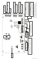
G N OUT1 and OUT2 Battery + 24VDC – L + BAT – 25A Relock delay adjustment. Used to hold OUT1 or OUT2 energized after a momentary closure across IN1 or IN2. Set for 0 seconds for output to follow input. Turn clockwise to increase time. 6.3A 6.3A 250V AC 25A 32V MIN Fire Alarm Interface – OUT2 + OUT1 OUT2 TIMER TIMER ON Connect these terminals to a normally closed dry contact that opens upon fire alarm activation.
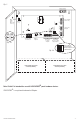
A T– ery uts ON IN2 GND GND C NO C NO C NO C NO FACP and Access Control Trigger Inputs FACP GND IN1 Fig. 3b 1 2 3 4 Option 1-Option 2 24-5V Hold Voltage Follow-up Delay 0.5-1 sec. Fire Alarm Interface GND IN2 GND Delayed 1 Follower 1 Delayed 2 Follower 2 C NO C NO C NO C NO Optional Rechargeable Stand-by Battery C NO C NO C NO C NO Class 2 Dry Outputs Note: StrikeIt1 is intended for use with VON DUPRIN® panic hardware devices. VON DUPRIN® is a registered trademark of Allegion.
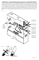
NEC Power-Limited Wiring Requirements for StrikeIt1V Model: Power-limited and non power-limited circuit wiring must remain separated in the cabinet. All power-limited circuit wiring must remain at least 0.25” away from any non power-limited circuit wiring. Furthermore, all power-limited circuit wiring and non power-limited circuit wiring must enter and exit the cabinet through different conduits. One such example of this is shown below.
Maintenance: Unit should be tested at least once a year for the proper operation as follows: FACP Supervision: To ensure proper connection and operation of the Fire Alarm disconnect hookup, remove wire from the terminal marked [FACP] on StrikeIt1V. With the DIP switch [SW4] in ON positon, unlocked Panic Hardware Devices will unlock. With DIP switch [SW4] in the OFF position (Fig. 3b, pg. 9), locked Panic Hardware Devices will relock.
Enclosure Dimensions: 13.5” x 13” x 3.25” (342.9mm x 330.2mm x 82.6mm) 1.40” (35.6mm) 4.85” (123.2mm) 4.85” (123.2mm) 1.40” (35.6mm) 1.20” (30.5mm) 0.75” (19.1mm) 3.25” (82.6mm) 1.20” (30.5mm) 0.75” (19.1mm) 12.5” (317.5mm) 11.0” (279.4mm) 1.20” (30.5mm) 0.9375” (23.8mm) 1.40” (35.6mm) 1.40” (35.6mm) 5.10” (129.5mm) 5.10” (129.5mm) 13.0” (330.2mm) 6.5625” (166.7mm) 5.10” (129.5mm) 0.9375” (23.8mm) 3.25” (82.6mm) 3.25” (82.6mm) 3.25” (82.6mm) 1.0” (25.4mm) 1.0” (25.4mm) 10.5” (266.