
Installation Instructions


- 4 - StrikeIt1
StrikeIt1 LED Diagnostics (cont’d):
INP2 - Red
TriggerInput2
On Output2-Energized.
SlowBlink Output2-OpenCircuit.
RapidBlink Output2-ShortCircuit.
Off Output2-De-energized.
FAI - Green
On FACP Input triggered (alarm condition).
Off FACP normal (non-alarm condition).
BATTrouble
Red
Off Normal condition.
On Manual test initiated.
SlowBlink Batterylowormissing,activeduringmanualtestorACfailure.
ACTrouble
Green
Off AC normal.
Slow blink AC low or missing.
Maintenance:
Unit should be tested at least once a year for the proper operation as follows:
FACP Supervision:ToensureproperconnectionandoperationoftheFireAlarmdisconnecthookup,removewirefrom
theterminalmarked[FACP]onStrikeIt1.Withthedipswitch[SW4]inONpositon,unlockedPanicHardwareDeviceswill
unlock.Withdipswitch[SW4]intheOFFposition(Fig. 3b, pg. 7), locked Panic Hardware Devices will relock.
Output Voltage Test: Under normal load conditions the DC output voltage should be checked for proper voltage level.
Battery Test: Under normal load conditions check that the battery is fully charged, check specified voltage both at
batteryterminalandattheboardterminalsmarked[+BAT--]toensurethereisnobreakinthebatteryconnectionwires.
PressManualtestbutton.ThebatteryLEDshouldbeilluminatedduringtheselftest(approximately15seconds.
When the battery LED blinks slowly this indicates that the battery is low or missing and may need to be replaced or serviced.
Note: Maximum charging current under discharge is 650mA.
Note: Expected battery life is 5 years, however it is recommended changing batteries in 4 years or less if needed.
Caution: For continuous protection against risk of electric shock and fire hazard, replace input fuse with the same type
andrating:6.3amp/250V.Donotexposetorainormoisture;indooruseonly.
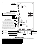
StrikeIt1 Terminal Identification:
Terminal Legend Function/Description
+ 12VDC – 12VDCAuxiliaryOutput@0.75ampinalarm,0.5ampinstand-by.
+ 24VDC – 24VDCAuxiliaryOutput@0.75amp.20VDCto26.4VDCforapplicationswithbatteryback-up.
+BAT– 24VDCStand-byBatteryConnection(Two(2)12VDCbatterieswiredinseries).
–OUT1+
Connect 24VDC Panic Hardware Device #1
(See compatibility chart for other UL Listed devices operating range of the device must cover
20VDC to 26.4VDC range 0.25 ohm maximum wiring resistance).
–OUT2+
Connect 24VDC Panic Hardware Device #2.
(See compatibility chart for other UL Listed devices operating range of the device must cover
20VDC to 26.4VDC range 0.25 ohm maximum wiring resistance).
FACP / GND
Normally Closed Dry Contact from Fire Alarm Control
(100 ohm maximum wiring resistance).
IN1 / GND
NormallyOpenTriggerinputcontrolsOutput1.Maybeheldclosedforextendedunlocking
(100 ohm maximum wiring resistance).
IN2 / GND
NormallyOpenTriggerinputcontrolsOutput2.Maybeheldclosedforextendedunlocking
(100 ohm maximum wiring resistance).
Delayed 1
Dryform“A”contactsprovidea1secondmomentarypulseafterapresetdelay.Withdipswitch[SW3]intheOFF
position,thedelayis0.5seconds.Withdipswitch[SW3]intheONposition,thedelayis1second(Fig. 3b, pg. 7).
ThispermitsthePanicHardwareDevicetofullyunlockbeforesignalingautooperatortoswingdoor.
Delayed 2
Dryform“A”contactsprovidea1secondmomentarypulseafterapresetdelay.Withdipswitch[SW3]intheOFF
position,thedelayis0.5seconds.Withdipswitch[SW3]intheONposition,thedelayis1second(Fig. 3b, pg. 7).
ThispermitsthePanicHardwareDevicetofullyunlockbeforesignalingautooperatortoswingdoor.
Follower 1
Dryform“A”contact.Energizeswhileoutput1isenergized.EnablesoutsideADAswitchplatetoactuate
auto operator while door is unlocked. De-activates outside ADA actuator while door is locked.
Follower 2
Dryform“A”contact.Energizeswhileoutput2isenergized.EnablesoutsideADAswitchplatetoactuate
auto operator while door is unlocked. De-activates outside ADA actuator while door is locked.
Supervision
Indicates low DC output voltage condition. It may be caused by an AC brownout and low battery occuring
simultaneously. Manual self test needs to be conducted to determine battery condition.